
Page 119 - Electrical Equipment Handbook _ Troubleshooting and Maintenance
P. 119
INDUCTION MOTORS
6.8 CHAPTER SIX
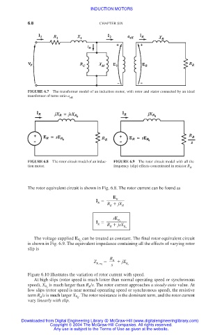
FIGURE 6.7 The transformer model of an induction motor, with rotor and stator connected by an ideal
transformer of turns ratio a eff.
FIGURE 6.8 The rotor circuit model of an induc- FIGURE 6.9 The rotor circuit model with all the
tion motor. frequency (slip) effects concentrated in resistor R .
R
The rotor equivalent circuit is shown in Fig. 6.8. The rotor current can be found as
E
R
I
R R jX R
R
sE
I
R 0
R R jsX R 0
R
The voltage supplied E R can be treated as constant. The final rotor equivalent circuit
0
is shown in Fig. 6.9. The equivalent impedance containing all the effects of varying rotor
slip is
R
Z R jX
R, eq R 0
s
Figure 6.10 illustrates the variation of rotor current with speed.
At high slips (rotor speed is much lower than normal operating speed or synchronous
is much larger than R /s. The rotor current approaches a steady-state value. At
speed), X R 0 R
low slips (rotor speed is near normal operating speed or synchronous speed), the resistive
term R /s is much larger X R . The rotor resistance is the dominant term, and the rotor current
R 0
vary linearly with slip.
Downloaded from Digital Engineering Library @ McGraw-Hill (www.digitalengineeringlibrary.com)
Copyright © 2004 The McGraw-Hill Companies. All rights reserved.
Any use is subject to the Terms of Use as given at the website.