
Page 122 - Electrical Equipment Handbook _ Troubleshooting and Maintenance
P. 122
INDUCTION MOTORS
INDUCTION MOTORS 6.11
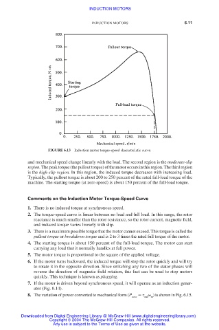
FIGURE 6.13 Induction motor torque-speed characteristic curve.
and mechanical speed change linearly with the load. The second region is the moderate-slip
region. The peak torque (the pullout torque) of the motor occurs in this region. The third region
is the high-slip region. In this region, the induced torque decreases with increasing load.
Typically, the pullout torque is about 200 to 250 percent of the rated full-load torque of the
machine. The starting torque (at zero speed) is about 150 percent of the full-load torque.
Comments on the Induction Motor Torque-Speed Curve
1. There is no induced torque at synchronous speed.
2. The torque-speed curve is linear between no load and full load. In this range, the rotor
reactance is much smaller than the rotor resistance, so the rotor current, magnetic field,
and induced torque varies linearly with slip.
3. There is a maximum possible torque that the motor cannot exceed. This torque is called the
pullout torque or breakdown torque and is 2 to 3 times the rated full torque of the motor.
4. The starting torque is about 150 percent of the full-load torque. The motor can start
carrying any load that it normally handles at full power.
5. The motor torque is proportional to the square of the applied voltage.
6. If the motor turns backward, the induced torque will stop the rotor quickly and will try
to rotate it in the opposite direction. Since switching any two of the stator phases will
reverse the direction of magnetic field rotation, this fact can be used to stop motors
quickly. This technique is known as plugging.
7. If the motor is driven beyond synchronous speed, it will operate as an induction gener-
ator (Fig. 6.14).
8. The variation of power converted to mechanical form (P ) is shown in Fig. 6.15.
conv ind m
Downloaded from Digital Engineering Library @ McGraw-Hill (www.digitalengineeringlibrary.com)
Copyright © 2004 The McGraw-Hill Companies. All rights reserved.
Any use is subject to the Terms of Use as given at the website.