
Page 127 - Electrical Equipment Handbook _ Troubleshooting and Maintenance
P. 127
INDUCTION MOTORS
6.16 CHAPTER SIX
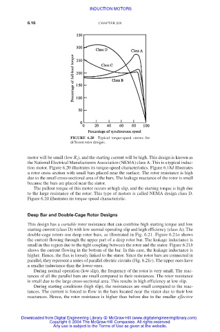
FIGURE 6.20 Typical torque-speed curves for
different rotor designs.
motor will be small (low R ), and the starting current will be high. This design is known as
2
the National Electrical Manufacturers Association (NEMA) class A. This is a typical induc-
tion motor. Figure 6.20 illustrates its torque-speed characteristics. Figure 6.18d illustrates
a rotor cross section with small bars placed near the surface. The rotor resistance is high
due to the small cross-sectional area of the bars. The leakage reactance of the rotor is small
because the bars are placed near the stator.
The pullout torque of this motor occurs at high slip, and the starting torque is high due
to the large resistance of the rotor. This type of motors is called NEMA design class D.
Figure 6.20 illustrates its torque-speed characteristic.
Deep Bar and Double-Cage Rotor Designs
This design has a variable rotor resistance that can combine high starting torque and low
starting current (class D) with low normal operating slip and high efficiency (class A). The
double-cage rotors use deep rotor bars, as illustrated in Fig. 6.21. Figure 6.21a shows
the current flowing through the upper part of a deep rotor bar. The leakage inductance is
small in this region due to the tight coupling between the rotor and the stator. Figure 6.21b
shows the current flowing in the bottom of the bar. In this case, the leakage inductance is
higher. Hence, the flux is loosely linked to the stator. Since the rotor bars are connected in
parallel, they represent a series of parallel electric circuits (Fig. 6.21c). The upper ones have
a smaller inductance than the lower ones.
During normal operation (low slip), the frequency of the rotor is very small. The reac-
tances of all the parallel bars are small compared to their resistances. The rotor resistance
is small due to the large cross-sectional area. This results in high efficiency at low slip.
During starting conditions (high slip), the resistances are small compared to the reac-
tances. The current is forced to flow in the bars located near the stator due to their low
reactances. Hence, the rotor resistance is higher than before due to the smaller effective
Downloaded from Digital Engineering Library @ McGraw-Hill (www.digitalengineeringlibrary.com)
Copyright © 2004 The McGraw-Hill Companies. All rights reserved.
Any use is subject to the Terms of Use as given at the website.