
Page 115 - Electrical Equipment Handbook _ Troubleshooting and Maintenance
P. 115
INDUCTION MOTORS
6.4 CHAPTER SIX
(a)
(b)
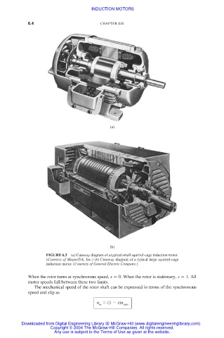
FIGURE 6.3 (a) Cutaway diagram of a typical small squirrel-cage induction motor.
(Courtesy of MagneTek, Inc.) (b) Cutaway diagram of a typical large squirrel-cage
induction motor. (Courtesy of General Electric Company.)
When the rotor turns at synchronous speed, s 0. When the rotor is stationary, s 1. All
motor speeds fall between these two limits.
The mechanical speed of the rotor shaft can be expressed in terms of the synchronous
speed and slip as
n (1 s)n sync
m
Downloaded from Digital Engineering Library @ McGraw-Hill (www.digitalengineeringlibrary.com)
Copyright © 2004 The McGraw-Hill Companies. All rights reserved.
Any use is subject to the Terms of Use as given at the website.