
Page 110 - Electrical Equipment Handbook _ Troubleshooting and Maintenance
P. 110
AC MACHINE FUNDAMENTALS
AC MACHINE FUNDAMENTALS 5.11
of thumb indicates that the life of an ac machine is halved for a temperature rise of 10 per-
cent above the rated temperature of the windings.
The temperature limits of machine insulation have been standardized by the National
Electrical Manufacturers Association (NEMA). A series of insulation system classes have
been defined. Each insulation system class specifies the maximum temperature rise
allowed for the insulation. The most common NEMA insulation classes for ac motors are
B, F, and H. Each class has a higher permissible winding temperature than the one before
it. For example, the temperature rise above ambient of the armature windings in continu-
ously operating induction machines is limited to 80°C for class B, 105°C for class F, and
125°C for class H insulation.
Similar standards have been defined by the International Electrotechnical Commission
(IEC) and by other national standards organizations.
AC MACHINE POWER FLOW AND LOSSES
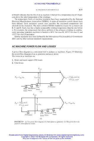
A power flow diagram is a convenient tool to analyze ac machines. Figure 5.9 illustrates
the power flow diagram of an ac generator and an ac motor.
The losses in ac machines are
2
1. Rotor and stator copper (I R) losses
2. Core losses
P conv
P = app m ind m P out =3 V I cos or
in
A
√3 V I cos
L L
Core I 2 R losses
Stray Mechanical losses
losses losses
(a)
P conv
P =3 V I cos P = load m
A
out
in
√3 V I cos ind m
L L
Core Mechanical Stray
2
I R losses losses losses
losses
(b)
FIGURE 5.9 (a) The power flow diagram of a three-phase ac generator. (b) The power flow dia-
gram of a three-phase ac motor.
Downloaded from Digital Engineering Library @ McGraw-Hill (www.digitalengineeringlibrary.com)
Copyright © 2004 The McGraw-Hill Companies. All rights reserved.
Any use is subject to the Terms of Use as given at the website.