
Page 113 - Electrical Equipment Handbook _ Troubleshooting and Maintenance
P. 113
INDUCTION MOTORS
6.2 CHAPTER SIX
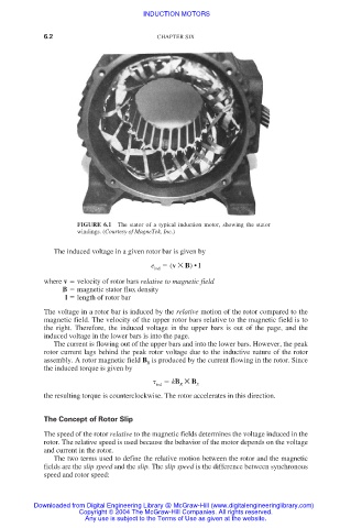
FIGURE 6.1 The stator of a typical induction motor, showing the stator
windings. (Courtesy of MagneTek, Inc.)
The induced voltage in a given rotor bar is given by
e ind (v × B) •l
where v velocity of rotor bars relative to magnetic field
B magnetic stator flux density
l length of rotor bar
The voltage in a rotor bar is induced by the relative motion of the rotor compared to the
magnetic field. The velocity of the upper rotor bars relative to the magnetic field is to
the right. Therefore, the induced voltage in the upper bars is out of the page, and the
induced voltage in the lower bars is into the page.
The current is flowing out of the upper bars and into the lower bars. However, the peak
rotor current lags behind the peak rotor voltage due to the inductive nature of the rotor
assembly. A rotor magnetic field B is produced by the current flowing in the rotor. Since
R
the induced torque is given by
kB × B
ind R S
the resulting torque is counterclockwise. The rotor accelerates in this direction.
The Concept of Rotor Slip
The speed of the rotor relative to the magnetic fields determines the voltage induced in the
rotor. The relative speed is used because the behavior of the motor depends on the voltage
and current in the rotor.
The two terms used to define the relative motion between the rotor and the magnetic
fields are the slip speed and the slip. The slip speed is the difference between synchronous
speed and rotor speed:
Downloaded from Digital Engineering Library @ McGraw-Hill (www.digitalengineeringlibrary.com)
Copyright © 2004 The McGraw-Hill Companies. All rights reserved.
Any use is subject to the Terms of Use as given at the website.