
Page 228 - Electrical Equipment Handbook _ Troubleshooting and Maintenance
P. 228
SYNCHRONOUS MACHINES
SYNCHRONOUS MACHINES 11.3
Stator. The stator is made of magnetic lam-
inations stacked axially. Insulating material
separates the laminations. It is made from
either varnish applied in a liquid form or oxides
formed in the heat-treating process. The lamina-
tions are held together by any of the following
methods:
● Bolts
● Welding the outer circumference of the lam-
inations
● Pressure bonding using the insulating material
as the bonding agent
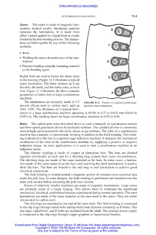
Radial bolts are used to fasten the stator stack
to the housing. Figure 11.3 illustrates a typical
stator lamination. The three sections in it are
the slots, the teeth, and the stator yoke, or back
iron. Figure 11.4 illustrates the three common
geometries of stator slots in large synchronous
machines.
The laminations are normally made of 3.5 FIGURE 11.3 Portion of a typical synchronous
percent silicon steel or carbon steel, such as machine stator lamination.
ASA 1020. The thickness of a typical lami-
nation in a large synchronous machine operating at 60 Hz is 0.37 to 0.635 mm (0.014 to
0.025 in). The stacking factor for large synchronous machines is 0.92 to 0.98.
Rotor. The salient-pole rotor described above is used commonly in synchronous motors
and slow-speed generators driven by hydraulic turbines. The cylindrical rotor is commonly
used in high-speed generators driven by steam or gas turbines. The rotor of a synchronous
machine has a damper, or amortisseur, winding in addition to the field winding. This wind-
ing is identical to the one in a squirrel-cage induction machine. It dampens the mechanical
oscillations of the rotor in the synchronous machine by supplying a positive or negative
induction torque. In some applications, it is used to start a synchronous machine as an
induction motor.
The damper winding is made of copper or aluminum bars. The bars are shorted
together electrically at each end by a shorting ring around their outer circumference.
The shorting rings are made of the same material as the bars. In some cases, a lamina-
tion made of the same material as the bars and matching the steel laminations is used to
short the bars. The bars are brazed to the end ring or end lamination to achieve good
electrical connection.
The field winding is wound around a magnetic section of constant cross-sectional area
under the pole face. In some designs, the field winding is preformed and installed over the
inner pole section before mounting the pole-face section.
Rotors of relatively smaller machines are made of magnetic laminations. Large rotors
are normally made of a single forging. This allows them to withstand the significant
mechanical, electrical, and thermal stresses experienced during normal operation. The rotor
laminations are made of the same material as the ones used in the stator. They are either
silicon steel or carbon steel.
The slip rings are mounted at one end of the rotor shaft. The field winding is connected
to the slip rings through radial bolts and up-shaft leads (known commonly as D bolts). The
slip rings, radial bolts, and D bolts are insulated from the shaft. The external power supply
is connected to the slip rings through copper-graphite or liquid-metal brushes.
Downloaded from Digital Engineering Library @ McGraw-Hill (www.digitalengineeringlibrary.com)
Copyright © 2004 The McGraw-Hill Companies. All rights reserved.
Any use is subject to the Terms of Use as given at the website.