
Page 45 - Electrical Equipment Handbook _ Troubleshooting and Maintenance
P. 45
TRANSFORMERS
3.2 CHAPTER THREE
i P (t) i (t)
S
(t) N (t)
v P N P S v S
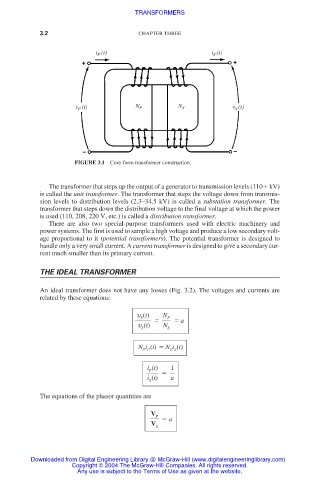
FIGURE 3.1 Core-form transformer construction.
The transformer that steps up the output of a generator to transmission levels (110 kV)
is called the unit transformer. The transformer that steps the voltage down from transmis-
sion levels to distribution levels (2.3–34.5 kV) is called a substation transformer. The
transformer that steps down the distribution voltage to the final voltage at which the power
is used (110, 208, 220 V, etc.) is called a distribution transformer.
There are also two special-purpose transformers used with electric machinery and
power systems. The first is used to sample a high voltage and produce a low secondary volt-
age proportional to it (potential transformers). The potential transformer is designed to
handle only a very small current. A current transformer is designed to give a secondary cur-
rent much smaller than its primary current.
THE IDEAL TRANSFORMER
An ideal transformer does not have any losses (Fig. 3.2). The voltages and currents are
related by these equations:
υ (t) N
P
P
a
υ (t) N
S S
N i (t) N i (t)
P P S S
i (t) 1
P
i (t) a
S
The equations of the phasor quantities are
V
P
a
V
S
Downloaded from Digital Engineering Library @ McGraw-Hill (www.digitalengineeringlibrary.com)
Copyright © 2004 The McGraw-Hill Companies. All rights reserved.
Any use is subject to the Terms of Use as given at the website.