
Page 46 - Electrical Equipment Handbook _ Troubleshooting and Maintenance
P. 46
TRANSFORMERS
TRANSFORMERS 3.3
i (t) i (t)
S
P
v (t) N P N S v S (t)
P
(a)
i (t) N P N S i (t)
S
P
(t) v (t)
v P S
i (t) N P N S i (t)
P
S
v P (t) v (t)
S
(b)
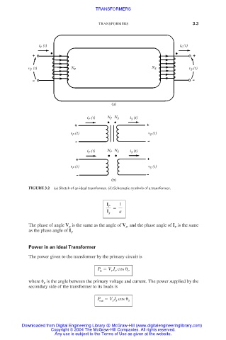
FIGURE 3.2 (a) Sketch of an ideal transformer. (b) Schematic symbols of a transformer.
I 1
P
I S a
The phase of angle V is the same as the angle of V , and the phase angle of I is the same
P S P
as the phase angle of I .
S
Power in an Ideal Transformer
The power given to the transformer by the primary circuit is
P V I cos
in P P P
where is the angle between the primary voltage and current. The power supplied by the
P
secondary side of the transformer to its loads is
P V I cos
out S S S
Downloaded from Digital Engineering Library @ McGraw-Hill (www.digitalengineeringlibrary.com)
Copyright © 2004 The McGraw-Hill Companies. All rights reserved.
Any use is subject to the Terms of Use as given at the website.