
Page 53 - Electrical Equipment Handbook _ Troubleshooting and Maintenance
P. 53
TRANSFORMERS
3.10 CHAPTER THREE
i (t)
P
(t)
v P N P N S v (t)
S
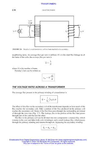
FIGURE 3.6 Sketch of a real transformer with no load attached to its secondary.
neighboring turns. An average flux per turn is defined. If is the total flux linkage in all
the turns of the coils, the average flux per turn is
N
where N is the number of turns.
Faraday’s law can be written as
d
e ind N
dt
THE VOLTAGE RATIO ACROSS A TRANSFORMER
The average flux present in the primary winding of a transformer is
1
υ (t) dt
P
N P
The effect of this flux on the secondary coil of the transformer depends on how much of the
flux reaches the secondary coil. Only a portion of the flux produced in the primary coil
reaches the secondary coil. Some of the flux lines pass through the surrounding air instead
of through the iron core (Fig. 3.7). The leakage flux is the portion of the flux that passes
through one of the coils but not the other.
The flux in the primary coil can be divided into two components: a mutual flux, which
remains in the core and links both coils (windings), and a small leakage flux, which passes
through the primary winding and returns through air, bypassing the secondary winding:
P M LP
Downloaded from Digital Engineering Library @ McGraw-Hill (www.digitalengineeringlibrary.com)
Copyright © 2004 The McGraw-Hill Companies. All rights reserved.
Any use is subject to the Terms of Use as given at the website.