
Page 58 - Electrical Equipment Handbook _ Troubleshooting and Maintenance
P. 58
TRANSFORMERS
TRANSFORMERS 3.15
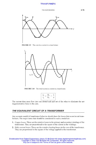
FIGURE 3.9 The core-loss current in a transformer.
i ex
t
(t)
v P
FIGURE 3.10 The total excitation current in a transformer.
1
N S
i P
≈
i S N P a
The current then must flow into one dotted end and out of the other to eliminate the net
magnetomotive force in the core.
THE EQUIVALENT CIRCUIT OF A TRANSFORMER
Any accurate model of transformer behavior should show the losses that occur in real trans-
formers. The major items that should be considered in such a model are
1. Copper losses. These are the resistive losses in the primary and secondary windings of the
transformer. They are proportional to the square of the current in the windings.
2. Eddy current losses. These are the resistive heating losses in the core of the transformer.
They are proportional to the square of the voltage applied to the transformer.
Downloaded from Digital Engineering Library @ McGraw-Hill (www.digitalengineeringlibrary.com)
Copyright © 2004 The McGraw-Hill Companies. All rights reserved.
Any use is subject to the Terms of Use as given at the website.