
Page 59 - Electrical Equipment Handbook _ Troubleshooting and Maintenance
P. 59
TRANSFORMERS
3.16 CHAPTER THREE
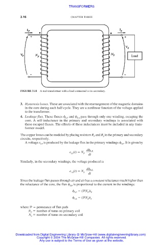
FIGURE 3.11 A real transformer with a load connected to its secondary.
3. Hysteresis losses. These are associated with the rearrangement of the magnetic domains
in the core during each half-cycle. They are a nonlinear function of the voltage applied
to the transformer.
4. Leakage flux. These fluxes and pass through only one winding, escaping the
LP LS
core. A self-inductance in the primary and secondary windings is associated with
these escaped fluxes. The effects of these inductances must be included in any trans-
former model.
The copper losses can be modeled by placing resistors R and R in the primary and secondary
S
P
circuits, respectively.
A voltage e is produced by the leakage flux in the primary windings . It is given by
LP
LP
d LP
e (t) N
P
LP
dt
Similarly, in the secondary windings, the voltage produced is
d LS
e (t) N
LS S dt
Since the leakage flux passes through air and air has a constant reluctance much higher than
the reluctance of the core, the flux is proportional to the current in the windings:
LP
( N )i
LP
P P
( N )i
LS S S
where permeance of flux path
N number of turns on primary coil
P
N number of turns on secondary coil
S
Downloaded from Digital Engineering Library @ McGraw-Hill (www.digitalengineeringlibrary.com)
Copyright © 2004 The McGraw-Hill Companies. All rights reserved.
Any use is subject to the Terms of Use as given at the website.