
Page 64 - Electrical Equipment Handbook _ Troubleshooting and Maintenance
P. 64
TRANSFORMERS
TRANSFORMERS 3.21
V P
a
R eq I cos X I sin
S
eq S
V S
I
j X eq S
R eq I S
I S
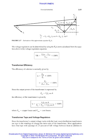
V P ≈ V S + R eq I S cos + X eq I S sin
a
FIGURE 3.17 Derivation of the approximate equation V /a.
P
The voltage regulation can be determined by using the V /a term calculated from the equa-
P
tion above in the voltage regulation equation:
V P/a V S,fl
VR 100%
V S,fl
Transformer Efficiency
The efficiency of a device is normally given by
P out
100%
P in
P out
100%
Pout Ploss
Since the output power of the transformer is expressed by
P V I cos
S S
out
the efficiency of the transformer is given by
V S I S cos
100%
P P core V I cos
Cu
S S
where P copper losses and P core losses.
Cu core
Transformer Taps and Voltage Regulators
Since the transformer’s output voltage varies with the load, most distribution transformers
use taps in the windings to change the turns ratio of the transformer. Most applications
have four taps with spacings of 2.5 percent of full voltage between them in addition to
Downloaded from Digital Engineering Library @ McGraw-Hill (www.digitalengineeringlibrary.com)
Copyright © 2004 The McGraw-Hill Companies. All rights reserved.
Any use is subject to the Terms of Use as given at the website.