
Page 65 - Electrical Equipment Handbook _ Troubleshooting and Maintenance
P. 65
TRANSFORMERS
3.22 CHAPTER THREE
the nominal setting. This arrangement permits a 5 percent adjustment above or below the
nominal voltage rating of the transformer.
The taps are adjusted normally when the transformer is deenergized. However, in some
applications, the transformer output voltage varies significantly with the load. These varia-
tions could be caused by large line impedance (possibly due to long distance) between the
generator and the load. Since normal loads require a steady voltage, these applications use a
tap changing under load (TCUL) transformer or voltage regulator. This transformer has the
ability to change the taps on power. A voltage regulator is a TCUL transformer that detects
the voltage and changes the taps automatically to maintain constant system voltage.
THE AUTOTRANSFORMER
In some applications, small adjustments in voltage are required. For example, the voltage
may need to be increased from 110 to115 V or from 13.2 to 13.6 kV. These changes could be
necessary to accommodate reductions in voltage that occur in power systems far from the gen-
erators. In these cases, it would be very expensive to have two full windings in the transformer.
The autotransformer is used in these applications instead of the conventional transformer.
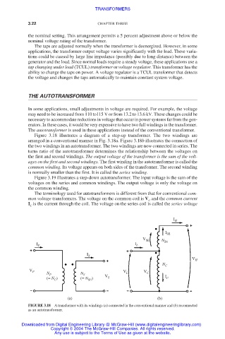
Figure 3.18 illustrates a diagram of a step-up transformer. The two windings are
arranged in a conventional manner in Fig. 3.18a. Figure 3.18b illustrates the connection of
the two windings in an autotransformer. The two windings are now connected in series. The
turns ratio of the autotransformer determines the relationship between the voltages on
the first and second windings. The output voltage of the transformer is the sum of the volt-
ages on the first and second windings. The first winding in the autotransformer is called the
common winding. Its voltage appears on both sides of the transformer. The second winding
is normally smaller than the first. It is called the series winding.
Figure 3.19 illustrates a step-down autotransformer. The input voltage is the sum of the
voltages on the series and common windings. The output voltage is only the voltage on
the common winding.
The terminology used for autotransformers is different from that for conventional com-
mon voltage transformers. The voltage on the common coil is V and the common current
C
I is the current through the coil. The voltage on the series coil is called the series voltage
C
I H
I SE
V SE N
I P I L SE
I S
V H
N C
V P V V
N P N S L C
(= N ) (= N ) V S I C
SE
C
(a) (b)
FIGURE 3.18 A transformer with its windings (a) connected in the conventional manner and (b) reconnected
as an autotransformer.
Downloaded from Digital Engineering Library @ McGraw-Hill (www.digitalengineeringlibrary.com)
Copyright © 2004 The McGraw-Hill Companies. All rights reserved.
Any use is subject to the Terms of Use as given at the website.