Page 62 - Electrical Equipment Handbook _ Troubleshooting and Maintenance
P. 62

TRANSFORMERS

                                       TRANSFORMERS                       3.19


                                       I S
               I P      R eq   j  X eq  a       aI P      R      j  X    I S
                          P       P                        eq S    eq S


                                               V              X
             V P   R c     j X m       aV S     P    R c     j  m         V S
                                               a     a 2      a 2


                           R eq   = R  + a R S                       R P
                                    2
                                 P
                             P                                  R eq  =  a 2  + R S
                                    2
            (a)            X eq   = X  + a  X S  (b)              S
                                 P
                             P                                       X
                                                                X eq   =  P  + X S
                                   I S                            S  a 2
                I P  R        X    a             aI P  R      X     I S
                      eq
                       P     j  eq P                   eq S  j  eq S
                                             V P
            V P                         aV S  a                          V S


             (c)                               (d)
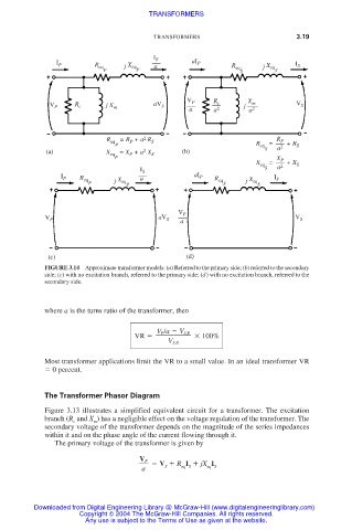
            FIGURE 3.14 Approximate transformer models: (a) Referred to the primary side; (b) referred to the secondary
            side; (c) with no excitation branch, referred to the primary side; (d) with no excitation branch, referred to the
            secondary side.


            where a is the turns ratio of the transformer, then


                                       V P /a   V S,fl
                                  VR               100%
                                          V S,fl
            Most transformer applications limit the VR to a small value. In an ideal transformer VR
              0 percent.


            The Transformer Phasor Diagram
            Figure 3.13 illustrates a simplified equivalent circuit for a transformer. The excitation
            branch (R and X ) has a negligible effect on the voltage regulation of the transformer. The
                   c
                        m
            secondary voltage of the transformer depends on the magnitude of the series impedances
            within it and on the phase angle of the current flowing through it.
              The primary voltage of the transformer is given by
                                        V   R I   jX I
                                   V P
                                    a    S   eq S   eq S


         Downloaded from Digital Engineering Library @ McGraw-Hill (www.digitalengineeringlibrary.com)
                    Copyright © 2004 The McGraw-Hill Companies. All rights reserved.
                      Any use is subject to the Terms of Use as given at the website.
   57   58   59   60   61   62   63   64   65   66   67