
Page 60 - Electrical Equipment Handbook _ Troubleshooting and Maintenance
P. 60
TRANSFORMERS
TRANSFORMERS 3.17
By substituting these equations into the previous ones, we get
d di p
2
e (t) N ( N ) i N
LP P P P P
dt dt
d di S
e (t) N ( N ) i N
2
LS S S S S
dt dt
By lumping the constants together, we get
di P
e (t) L
LP P
dt
di S
e (t) L
LS S
dt
where L and L are the self-inductances of the primary and secondary windings, respec-
P S
tively. Therefore, the leakage flux will be modeled as an inductor.
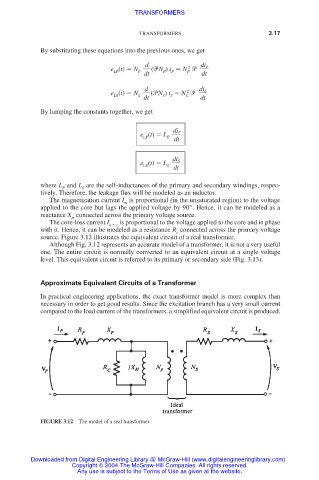
The magnetization current I is proportional (in the unsaturated region) to the voltage
m
applied to the core but lags the applied voltage by 90°. Hence, it can be modeled as a
reactance X connected across the primary voltage source.
m
The core-loss current I is proportional to the voltage applied to the core and in phase
h e
with it. Hence, it can be modeled as a resistance R connected across the primary voltage
c
source. Figure 3.12 illustrates the equivalent circuit of a real transformer.
Although Fig. 3.12 represents an accurate model of a transformer, it is not a very useful
one. The entire circuit is normally converted to an equivalent circuit at a single voltage
level. This equivalent circuit is referred to its primary or secondary side (Fig. 3.13).
Approximate Equivalent Circuits of a Transformer
In practical engineering applications, the exact transformer model is more complex than
necessary in order to get good results. Since the excitation branch has a very small current
compared to the load current of the transformers, a simplified equivalent circuit is produced.
FIGURE 3.12 The model of a real transformer.
Downloaded from Digital Engineering Library @ McGraw-Hill (www.digitalengineeringlibrary.com)
Copyright © 2004 The McGraw-Hill Companies. All rights reserved.
Any use is subject to the Terms of Use as given at the website.