
Page 69 - Electrical Equipment Handbook _ Troubleshooting and Maintenance
P. 69
TRANSFORMERS
3.26 CHAPTER THREE
magnetization current of the transformer. Figure 3.8a illustrates the magnetization curve of a
transformer. When a voltage υ(t) V sin
t V is applied to the primary winding of the trans-
M
former, the flux will be
V M
(t) cos
t
N P
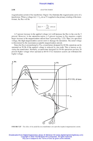
A 5 percent increase in the applied voltage υ(t) will increase the flux in the core by 5
percent. However, in the saturation region, a 5 percent increase in flux requires a much
larger increase in the magnetization current than 5 percent (Fig. 3.23). Thus, at a specified
voltage, this high magnetization current starts to damage the insulation. The rated voltage
is determined by the maximum acceptable magnetization current.
Since the flux is proportional to V/
, a transformer designed for 60-Hz operation can be
operated on 50 Hz if the applied voltage is reduced by one-sixth. This is known as de-
rating the transformer. Similarly, a transformer designed for 50-Hz operation can have 20
percent higher voltage when operated at 60 Hz if its insulation system can withstand the
higher voltage.
FIGURE 3.23 The effect of the peak flux in a transformer core upon the required magnetization current.
Downloaded from Digital Engineering Library @ McGraw-Hill (www.digitalengineeringlibrary.com)
Copyright © 2004 The McGraw-Hill Companies. All rights reserved.
Any use is subject to the Terms of Use as given at the website.