
Page 74 - Electrical Equipment Handbook _ Troubleshooting and Maintenance
P. 74
TRANSFORMER COMPONENTS AND MAINTENANCE
TRANSFORMER COMPONENTS AND MAINTENANCE 4.3
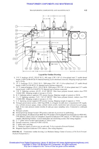
Legend for Outline Drawing
1. 3 H. V. bushings; 69 kV, 350 kV B.I.L. 400 amps, C/W 1.50"-12 silver-plated stud. 2" usable thread
length. LAPP Cat #B-88726-70. Internal bushing lead is drawlead connected. Shipping weight per bush-
ing is 139 lb.
2. 3 L. V. bushings; 25 kV, 150 kV B.I.L. 2000 amps, C/W 1.50"-12 silver-plated stud. 2.5" usable thread
length. LAPP Cat # B-88723-70. Internal lead is bottom connected.
3. 1 L. V. neutral bushings; 25 kV, 150 kV B.I.L. 2000 amps, C/W 1.50"-12 silver-plated stud. 2.5" usable
thread length. LAPP Cat # B-88723-70. Internal lead is bottom connected.
4. 3 H. V. lightning arresters, 60 kV, 48 kV MCOV. Ohio brass polymer housed, station class PVN
314048-3001. Shipping weight of arrester is 53.6 lb.
5. H. V. lightning arrester supports C/W seismic bracing. Shipping weight of supports is 304 lb.
6. 3 L. V. lightning arresters, 9 kV, 7.65 kV MCOV. Ohio brass polymer housed, station class PVN
314008-3001. Shipping weight of arrester is 21.3 lb.
7. L. V. lightning arrester supports C/W seismic bracing. Shipping weight of supports is 138 lb.
8. Nitrogen preservation system, ABB Type RNB, in a hinged, lockable door compartment C/W regula-
tors, cylinder pressure gauge, empty cylinder alarm switch, transformer tank pressure/vacuum gauge,
high- & low-tank-pressure alarm switches & tank gas space sampling valve. Connected to a nitrogen
cylinder.
9. Nitrogen cylinder.
10. Deenergized tap changer handle C/W position indicator & provision for padlocking.
11. Load tap changer, Reinhausen Type RMV-II, C/W Qualitrol Self-Sealing Pressure Relief Device #208-60U,
C/W deflector, alarm contacts & semaphore, liquid level indicator C/W contacts, 1 ⁄2" NPT drain valve with
1
sampler, dehydrating breather, vacuum interrupters and monitoring system. (See wiring diagram.)
12. 2 - 1" globe valves located approximately 6' below cover.
13. Ground connectors, Anderson # SW11-025-B.
14. 1" globe valve and plug.
15. 2 - Multiaxis impact recorders (one at each end). To be returned to Ferranti-Packard.
16. Magnetic liquid level indicator C/W contacts. (See wiring diagram.)
FIGURE 4.2 Transformer outline drawing, Los Medanos Energy Center (Courtesy of VA Tech Ferranti-
Packard Transformers.)
Downloaded from Digital Engineering Library @ McGraw-Hill (www.digitalengineeringlibrary.com)
Copyright © 2004 The McGraw-Hill Companies. All rights reserved.
Any use is subject to the Terms of Use as given at the website.