
Page 75 - Electrical Equipment Handbook _ Troubleshooting and Maintenance
P. 75
TRANSFORMER COMPONENTS AND MAINTENANCE
4.4 CHAPTER FOUR
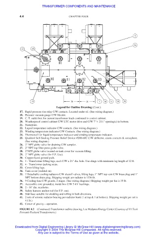
Legend for Outline Drawing (Cont.)
17. Rapid pressure rise relay C/W contacts. Located under oil. (See wiring diagram.)
18. Pressure vacuum gauge C/W bleeder.
19. C. T. outlet box for current transformer leads continued to control cabinet.
1
20. Weatherproof control cabinet C/W LTC motor drive and C/W 7" 21 ⁄4" opening(s) in bottom.
21. Nameplate.
22. Liquid temperature indicator C/W contacts. (See wiring diagram.)
23. Winding temperature indicator C/W Contacts. (See wiring diagram.)
24. Thermowell for liquid temperature indicator and winding temperature indicator.
25. Qualitrol Self-Sealing Pressure Relief Device #208-60U C/W deflector, alarm contacts & semaphore.
(See wiring diagram.)
26. 2" NPT globe valve for draining C/W sampler.
27. 2" NPT top filter press globe valve.
28. 2"NPT globe valve located on tank cover for vacuum filling.
29. 2" NPT globe valve (for F.P. Use).
30. Copper-faced ground pads.
31. 4 - Transformer lifting lugs, each C/W a 2 ⁄2" dia. hole. Use slings with minimum leg length of 12 ft.
1
32. 4 - Transformer jacking steps.
33. Cover lifting lugs.
34. Tank cover (welded on).
35. 7 Detachable cooling radiators C/W shutoff valves, lifting lugs, 1" NPT top vent C/W brass plug and 1"
NPT bottom drain plug. Shipping weight per radiator is 1336 lb.
36. 9 Cooling fans C/W guards, 2 stages. (See wiring diagram.) Shipping weight per fan is 35 lb.
37. Accessible core ground(s), inside box C/W 5-kV bushings.
38. 2 - 18" dia. manholes.
39. Safety harness anchor rod (for F.P. use).
40. Slab base suitable for skidding and rolling in both directions.
41. 2 sets of seismic radiator bracing per radiator bank (1 at top & 1 at bottom). Shipping weight per set is
41 lb.)
42. Center of gravity—operation.
FIGURE 4.2 (Continued) Transformer outline drawing, Los Medanos Energy Center (Courtesy of VA Tech
Ferranti-Packard Transformers.)
Downloaded from Digital Engineering Library @ McGraw-Hill (www.digitalengineeringlibrary.com)
Copyright © 2004 The McGraw-Hill Companies. All rights reserved.
Any use is subject to the Terms of Use as given at the website.