
Page 79 - Electrical Equipment Handbook _ Troubleshooting and Maintenance
P. 79
TRANSFORMER COMPONENTS AND MAINTENANCE
4.8 CHAPTER FOUR
and insulating barriers between the coils. The core is grounded at one point. The ground
connection is normally accessible externally for test purposes.
Windings
The windings must be able to withstand the large mechanical forces created by a short cir-
cuit. The winding insulation must be able to withstand the highest operating temperature
without excessive degradation. The cooling fluid must be able to flow freely through spaces
between the windings to remove the heat. The windings are arranged concentrically. The
highest voltage is located on the outside.
Nitrogen Demand System
Many transformers are equipped with an automatic nitrogen demand system. It regulates
the pressure in the transformer during the thermal cycles of the oil (swell and shrinkage
of the oil). Nitrogen is used as a buffer gas between the oil and the air. Its purpose is to
keep outside air (containing water vapor) from contacting the oil. The water vapor has
devastating effects on the oil. The dew point of nitrogen is less than 50°C to ensure that
it is very dry. Most units have an alarm indicating low nitrogen pressure in the cylinder.
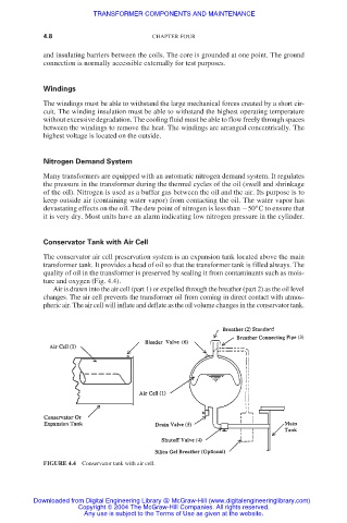
Conservator Tank with Air Cell
The conservator air cell preservation system is an expansion tank located above the main
transformer tank. It provides a head of oil so that the transformer tank is filled always. The
quality of oil in the transformer is preserved by sealing it from contaminants such as mois-
ture and oxygen (Fig. 4.4).
Air is drawn into the air cell (part 1) or expelled through the breather (part 2) as the oil level
changes. The air cell prevents the transformer oil from coming in direct contact with atmos-
pheric air. The air cell will inflate and deflate as the oil volume changes in the conservator tank.
FIGURE 4.4 Conservator tank with air cell.
Downloaded from Digital Engineering Library @ McGraw-Hill (www.digitalengineeringlibrary.com)
Copyright © 2004 The McGraw-Hill Companies. All rights reserved.
Any use is subject to the Terms of Use as given at the website.