
Page 73 - Electrical Equipment Handbook _ Troubleshooting and Maintenance
P. 73
TRANSFORMER COMPONENTS AND MAINTENANCE
4.2 CHAPTER FOUR
● Oil-immersed self-cooled (heat is removed by natural convection of the oil through radi-
ators)
● Oil-immersed cooled by forced air (heat is removed by blowers blowing air on radiators)
● Oil-immersed cooled by water (the oil is cooled by an oil-water heat exchanger)
The lowest rating of oil-type transformers is around 750 kVA. Since modern dry-type trans-
formers are being manufactured up to a rating of 20 MVA, they are replacing oil-type
transformers. The main reason is that oil-immersed transformers constitute a fire hazard, and
they are very hard to maintain. Dry-type transformers are preferred in most industries.
The rating of oil-immersed cooled-by-water transformers is normally higher than 100
MVA. However, they could be used for transformers having a rating as low as 10 MVA if
the transformer is feeding a rectifier. Harmonics (deformation in the sine wave of current
and voltage) are normally generated in this application, causing significant heat generation,
that necessitate cooling through a heat exchanger.
Most failures in transformers are caused by erosion of the insulating materials. Analysis
of a transformer’s oil can provide trends and early warning signs of premature failure.
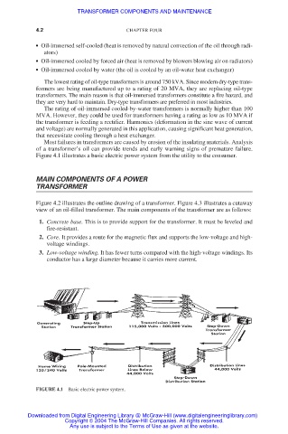
Figure 4.1 illustrates a basic electric power system from the utility to the consumer.
MAIN COMPONENTS OF A POWER
TRANSFORMER
Figure 4.2 illustrates the outline drawing of a transformer. Figure 4.3 illustrates a cutaway
view of an oil-filled transformer. The main components of the transformer are as follows:
1. Concrete base. This is to provide support for the transformer. It must be leveled and
fire-resistant.
2. Core. It provides a route for the magnetic flux and supports the low-voltage and high-
voltage windings.
3. Low-voltage winding. It has fewer turns compared with the high-voltage windings. Its
conductor has a large diameter because it carries more current.
FIGURE 4.1 Basic electric power system.
Downloaded from Digital Engineering Library @ McGraw-Hill (www.digitalengineeringlibrary.com)
Copyright © 2004 The McGraw-Hill Companies. All rights reserved.
Any use is subject to the Terms of Use as given at the website.