
Page 54 - Electrical Equipment Handbook _ Troubleshooting and Maintenance
P. 54
TRANSFORMERS
TRANSFORMERS 3.11
ø M
I P I S
ø LP ø LS
V P V S
ø M
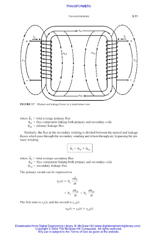
FIGURE 3.7 Mutual and leakage fluxes in a transformer core.
where total average primary flux
P
flux component linking both primary and secondary coils
M
primary leakage flux
LP
Similarly, the flux in the secondary winding is divided between the mutual and leakage
fluxes which pass through the secondary winding and return through air, bypassing the pri-
mary winding:
S M LS
where total average secondary flux
S
flux component linking both primary and secondary coils
M
secondary leakage flux
LS
The primary circuit can be expressed as
d
P
υ (t) N
P P dt
d M d LP
N N
P P
dt dt
The first term is e (t), and the second is e (t).
P LP
υ (t) e (t) e (t)
P
LP
P
Downloaded from Digital Engineering Library @ McGraw-Hill (www.digitalengineeringlibrary.com)
Copyright © 2004 The McGraw-Hill Companies. All rights reserved.
Any use is subject to the Terms of Use as given at the website.