
Page 94 - Electrical Equipment Handbook _ Troubleshooting and Maintenance
P. 94
TRANSFORMER COMPONENTS AND MAINTENANCE
TRANSFORMER COMPONENTS AND MAINTENANCE 4.23
TOUGH
CAST ALUMINUM
BODY
GAS
BLEEDER VALVE ACCUMULATION
Small to prevent CHAMBER MAGNETIC
wave shock tripping Gas build up INDICATOR
does not affect
of pressure switch operation of bellows
TILT-PROOF
BUTTON-TYPE
FLOAT MICROSWITCH
ALARM
LEADS
JOINT
Lower unit may
be used alone as
pressure
fault relay
BELLOWS PRESSURE
Seals out oil EQUALIZING
Compresses air to BUTTON SILICONE
flex diaphragm TYPE RUBBER
MICRO DIAPHRAGM
SWITCH AND SEAL
From transformer OIL AIR VENT
and gas collection INLET
system WATERPROOF
DIAPHRAGM PLUG
GAS AND OIL Actuates CONNECTOR
PRESSURE PRESSURE switch
TEST CONNECTION CHAMBER
BYPASS
3 EASY ATTACH
MOUNTING LUGS
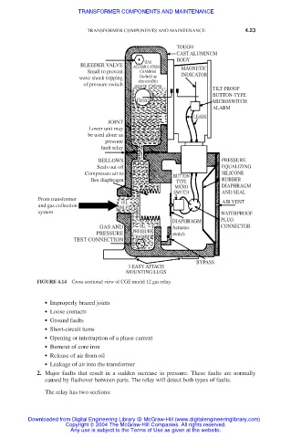
FIGURE 4.14 Cross-sectional view of CGE model 12 gas relay.
● Improperly brazed joints
● Loose contacts
● Ground faults
● Short-circuit turns
● Opening or interruption of a phase current
● Burnout of core iron
● Release of air from oil
● Leakage of air into the transformer
2. Major faults that result in a sudden increase in pressure. These faults are normally
caused by flashover between parts. The relay will detect both types of faults.
The relay has two sections:
Downloaded from Digital Engineering Library @ McGraw-Hill (www.digitalengineeringlibrary.com)
Copyright © 2004 The McGraw-Hill Companies. All rights reserved.
Any use is subject to the Terms of Use as given at the website.