
Page 237 - Electrical Safety of Low Voltage Systems
P. 237
220 Chapter Thirteen
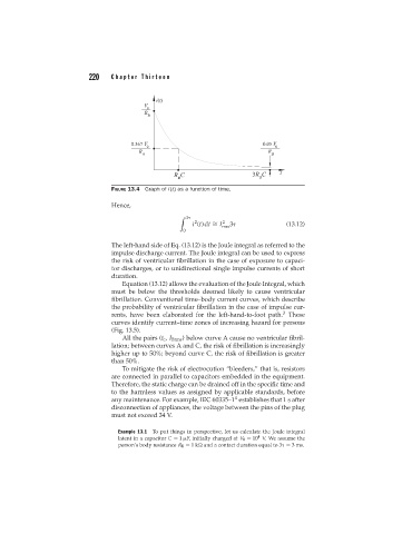
FIGURE 13.4 Graph of i(t) as a function of time.
Hence,
3
2
i (t)dt = I 2 3 (13.12)
∼
rms
0
The left-hand side of Eq. (13.12) is the Joule integral as referred to the
impulse discharge current. The Joule integral can be used to express
the risk of ventricular fibrillation in the case of exposure to capaci-
tor discharges, or to unidirectional single impulse currents of short
duration.
Equation (13.12) allows the evaluation of the Joule Integral, which
must be below the thresholds deemed likely to cause ventricular
fibrillation. Conventional time–body current curves, which describe
the probability of ventricular fibrillation in the case of impulse cur-
3
rents, have been elaborated for the left-hand-to-foot path. These
curves identify current–time zones of increasing hazard for persons
(Fig. 13.5).
All the pairs (t c , I Brms ) below curve A cause no ventricular fibril-
lation; between curves A and C, the risk of fibrillation is increasingly
higher up to 50%; beyond curve C, the risk of fibrillation is greater
than 50%.
To mitigate the risk of electrocution “bleeders,” that is, resistors
are connected in parallel to capacitors embedded in the equipment.
Therefore, the static charge can be drained off in the specific time and
to the harmless values as assigned by applicable standards, before
4
any maintenance. For example, IEC 60335–1 establishes that 1 s after
disconnection of appliances, the voltage between the pins of the plug
must not exceed 34 V.
Example 13.1 To put things in perspective, let us calculate the Joule integral
4
latent in a capacitor C = 1 F, initially charged at V 0 = 10 V. We assume the
person’s body resistance R B = 1k and a contact duration equal to 3 = 3 ms.