
Page 242 - Electrical Safety of Low Voltage Systems
P. 242
Testing the Electrical Safety 225
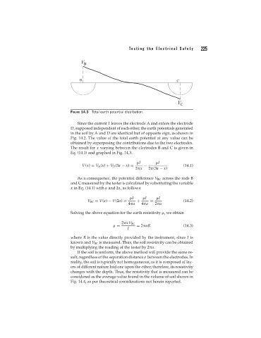
FIGURE 14.3 Total earth potential distribution.
Since the current I leaves the electrode A and enters the electrode
D, supposed independent of each other, the earth potentials generated
in the soil by A and D are identical but of opposite sign, as shown in
Fig. 14.2. The value of the total earth potential at any value can be
obtained by superposing the contributions due to the two electrodes.
The result for x varying between the electrodes B and C is given in
Eq. (14.1) and graphed in Fig. 14.3.
I I
V(x) = V A (x) + V D (3a − x) = − (14.1)
2 x 2 (3a − x)
As a consequence, the potential difference V BC across the rods B
and C measured by the tester is calculated by substituting the variable
x in Eq. (14.1) with a and 2a, as follows:
I I I
V BC = V(a) − V(2a) = + = (14.2)
4 a 4 a 2 a
Solving the above equation for the earth resistivity , we obtain
2 aV BC
= = 2 aR (14.3)
I
where R is the value directly provided by the instrument, since I is
known and V BC is measured. Thus, the soil resistivity can be obtained
by multiplying the reading of the tester by 2 a.
If the soil is uniform, the above method will provide the same re-
sult, regardless of the separation distance a between the electrodes. In
reality, the soil is typically not homogeneous, as it is composed of lay-
ers of different nature laid one upon the other; therefore, its resistivity
changes with the depth. Thus, the resistivity that is measured can be
considered as the average value found in the volume of soil shown in
Fig. 14.4, as per theoretical considerations not herein reported.