
Page 247 - Electrical Safety of Low Voltage Systems
P. 247
230 Chapter Fourteen
is effective in preventing parts of fault currents from flowing through
ground, thereby lowering touch and step voltages at the user’s
premises. During the measurement, this connection must be removed
at both ends, so that the entire test current will return to the source
through the earth, allowing the proper determination of the unknown
ground grid resistance.
14.5 Earth Resistance Measurement in TT Systems
As discussed in Chap. 6, the fault-loop in TT systems includes both
the ground resistance R G of the consumer’s electrode and the utility’s
electrode earth resistance R N , which are independent of each other
(Fig. 6.1). In the assumption that R G R N , which holds true especially
in urban areas, a simplified method to measure the earth resistance of
the user’s electrode may be adopted.
With the aforementioned method, which does not require any aux-
iliary electrode, the total fault-loop resistance is measured, and the
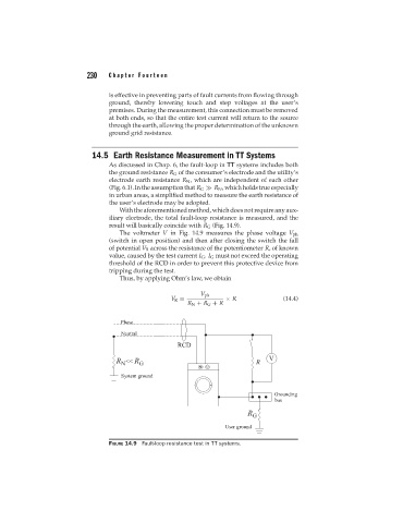
result will basically coincide with R G (Fig. 14.9).
The voltmeter V in Fig. 14.9 measures the phase voltage V ph
(switch in open position) and then after closing the switch the fall
of potential V R across the resistance of the potentiometer R, of known
value, caused by the test current I G . I G must not exceed the operating
threshold of the RCD in order to prevent this protective device from
tripping during the test.
Thus, by applying Ohm’s law, we obtain
V ph
V R = × R (14.4)
R N + R G + R
FIGURE 14.9 Fault-loop resistance test in TT systems.