
Page 252 - Electrical Safety of Low Voltage Systems
P. 252
Testing the Electrical Safety 235
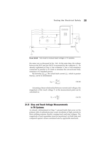
FIGURE 14.13 Test circuit to measure touch voltages in TN systems.
the same way as discussed in Sec. 14.6. At the same time, the voltage
between the ECP and the EXCP is measured by the voltmeter V 1 .As
already explained in Chap. 4, the voltmeter V 1 has a 1-k resistance
connected in parallel to its leads to simulate the conventional body
resistance of a standard person.
By knowing |Z Loop |, the actual fault current |I G |, which is greater
than |I|, can be so determined:
|V |
ph
|I |= (14.14)
G
|Z |
Loop
Assuming a linear relationship between currents and voltages, the
magnitude of the touch voltage V T at the measurement point can be
calculated as:
|I |
G
V T = V 1 (14.15)
|I|
14.8 Step and Touch Voltage Measurements
in TN Systems
As already substantiated in Chap. 7, ground faults that occur on the
primary side of substations may cause circulation of high currents in
their earthing systems, thereby causing touch and step voltages. The
magnitude of such quantities must be ascertained via field tests and
compared against values considered safe by applicable standards.