
Page 255 - Electrical Safety of Low Voltage Systems
P. 255
238 Chapter Fourteen
β
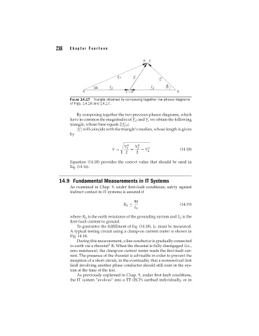
FIGURE 14.17 Triangle obtained by composing together the phasor diagrams
of Figs. 14.16 and 14.17.
By composing together the two previous phasor diagrams, which
have in common the magnitudes of V d and V, we obtain the following
triangle, whose base equals 2|V d |.
|V| will coincide with the triangle’s median, whose length is given
by
V 1 2 V 2 2
V = + − V d 2 (14.18)
2 2
Equation (14.18) provides the correct value that should be used in
Eq. (14.16).
14.9 Fundamental Measurements in IT Systems
As examined in Chap. 9, under first-fault conditions, safety against
indirect contact in IT systems is assured if
50
R G ≤ (14.19)
I G
where R G is the earth resistance of the grounding system and I G is the
first-fault current to ground.
To guarantee the fulfillment of Eq. (14.18), I G must be measured.
A typical testing circuit using a clamp-on current meter is shown in
Fig. 14.18.
During this measurement, a line conductor is gradually connected
3
to earth via a rheostat R. When the rheostat is fully disengaged (i.e.,
zero resistance), the clamp-on current meter reads the first-fault cur-
rent. The presence of the rheostat is advisable in order to prevent the
inception of a short circuit, in the eventuality that a nonresolved first
fault involving another phase conductor should still exist in the sys-
tem at the time of the test.
As previously explained in Chap. 9, under first-fault conditions,
the IT system “evolves” into a TT (ECPs earthed individually, or in