
Page 257 - Electrical Safety of Low Voltage Systems
P. 257
240 Chapter Fourteen
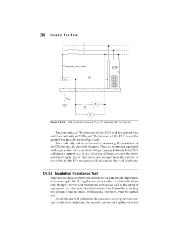
FIGURE 14.19 Test circuit to measure Z S in IT systems with no neutral.
The continuity of PEs between all the ECPs and the ground bus,
and the continuity of MEBs and SBs between all the EXCPs and the
ground bus must be tested (Fig. 14.20).
The continuity test is not aimed at measuring the resistance of
the PE, but only its electrical integrity. Thus, an ohmmeter equipped
with a generator with a no-load voltage ranging between 4 and 24 V
will inject a current (a.c. or d.c.) of at least 200 mA between the afore-
mentioned metal parts. This test is also referred to as the soft test. A
low value for the PE’s resistance will indicate its electrical continuity.
14.11 Insulation Resistance Test
High insulation levels between circuits are of paramount importance
in preventing faults. During the normal operation of the electrical sys-
tem, though, thermal and mechanical stresses, as well as the aging of
equipment, can decrease the effectiveness of such insulation, making
the system prone to faults. Verifications, therefore, must be carried
out.
An ohmmeter will determine the resistance existing between cir-
cuit conductors, including the neutral, connected together or taken