
Page 258 - Electrical Safety of Low Voltage Systems
P. 258
Testing the Electrical Safety 241
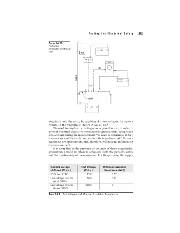
FIGURE 14.20
Protective
conductor continuity
test.
singularly, and the earth, by applying d.c. test voltages, for up to a
minute, of the magnitudes shown in Table 14.1. 4
We need to employ d.c. voltages as opposed to a.c., in order to
prevent eventual capacitive reactances-to-ground from being taken
into account during the measurement. We want to determine, in fact,
the resistance of the insulation, and not its impedance. At 0 Hz such
reactances are open circuits, and, therefore, will have no influence on
the measurement.
It is clear that in the presence of voltages of these magnitudes,
precautions should be taken to safeguard both the person’s safety
and the functionality of the equipment. For this purpose, the supply
Nominal Voltage Test Voltage Minimum Insulation
of Circuit (V a.c.) (V d.c.) Resistance (MΩ)
SELV and PELV 250 0.25
Low-voltage circuits 500 0.5
up to 500 V
Low-voltage circuits 1000 1
above 500 V
TABLE 14.1 Test Voltages and Minimum Insulation Resistances