
Page 253 - Electrical Safety of Low Voltage Systems
P. 253
236 Chapter Fourteen
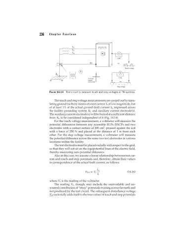
FIGURE 14.14 Test circuit to measure touch and step voltages in TN systems.
The touch and step voltage measurements are carried out by simu-
lating ground faults by means of a test current I t of low magnitude, but
of at least 1% of the actual ground-fault current I G impressed across
the facility grounding system R G and auxiliary current electrode(s).
The auxiliary current electrode(s) will be buried at a sufficient distance
from R G to be considered independent of it (Fig. 14.14).
For the touch voltage measurement, a voltmeter will measure the
potential differences between any accessible ECPs/EXCPs and two
2
electrodes with a contact surface of 200 cm , pressed against the soil
with a force of 250 N and placed at the distance of 1 m from each
other. For the step voltage measurement, a voltmeter will measure
the potential difference across the same two test electrodes in various
locations within the facility.
The test electrodes must be placed radially with respect to the grid,
so that they will not sit on the equipotential lines of the electric field,
thereby measuring zero potential difference.
Also in this case, we assume a linear relationship between test cur-
rent and touch and step potentials and, therefore, obtain their values
in correspondence of the actual fault current, as follows:
I G
V T,S = V 1 (14.16)
I t
where V 1 is the reading of the voltmeter.
The reading V 1 , though, may include the unavoidable and un-
wanted contribution of “stray” potentials existing across the earth and
not produced by the test circuit. The subsequent disturbance voltage
V d vectorially adds itself to the true values of touch and step potentials