Page 250 - Electrical Safety of Low Voltage Systems
P. 250

Testing the Electrical Safety    233
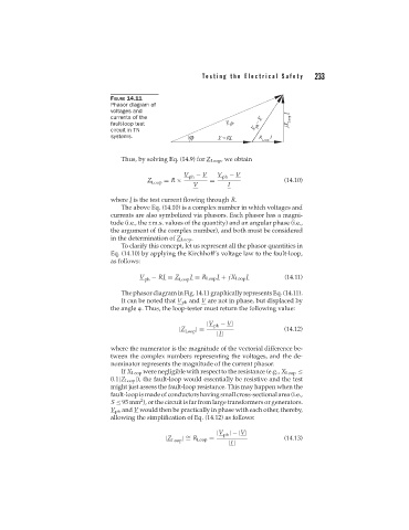

                                  FIGURE 14.11
                                  Phasor diagram of
                                  voltages and
                                  currents of the
                                  fault-loop test
                                  circuit in TN
                                  systems.


                                     Thus, by solving Eq. (14.9) for Z Loop , we obtain

                                                        V ph  − V  V ph  − V
                                             Z    = R ×         =                     (14.10)
                                              Loop
                                                           V         I
                                  where I is the test current flowing through R.
                                     The above Eq. (14.10) is a complex number in which voltages and
                                  currents are also symbolized via phasors. Each phasor has a magni-
                                  tude (i.e., the r.m.s. values of the quantity) and an angular phase (i.e.,
                                  the argument of the complex number), and both must be considered
                                  in the determination of Z Loop .
                                     To clarify this concept, let us represent all the phasor quantities in
                                  Eq. (14.10) by applying the Kirchhoff’s voltage law to the fault-loop,
                                  as follows:

                                           V  − RI = Z    I = R Loop I + jX Loop I    (14.11)
                                            ph         Loop
                                     The phasor diagram in Fig. 14.11 graphically represents Eq. (14.11).
                                     It can be noted that V ph and V are not in phase, but displaced by
                                  the angle  . Thus, the loop-tester must return the following value:

                                                               |V ph  − V|
                                                      |Z Loop |=                      (14.12)
                                                                  |I|

                                  where the numerator is the magnitude of the vectorial difference be-
                                  tween the complex numbers representing the voltages, and the de-
                                  nominator represents the magnitude of the current phasor.
                                     If X Loop were negligible with respect to the resistance (e.g., X Loop ≤
                                  0.1|Z Loop |), the fault-loop would essentially be resistive and the test
                                  might just assess the fault-loop resistance. This may happen when the
                                  fault-loop is madeof conductors havingsmall cross-sectionalarea (i.e.,
                                           2
                                  S ≤ 95 mm ), or the circuit is far from large transformers or generators.
                                  V ph and V would then be practically in phase with each other, thereby,
                                  allowing the simplification of Eq. (14.12) as follows:

                                                                  |V |−|V|
                                                                    ph
                                                  |Z Loop | = R Loop =                (14.13)
                                                         ∼
                                                                     |I|
   245   246   247   248   249   250   251   252   253   254   255