
Page 245 - Electrical Safety of Low Voltage Systems
P. 245
228 Chapter Fourteen
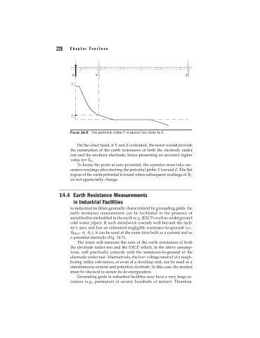
FIGURE 14.6 The potential probe Y is placed too close to X.
On the other hand, if Y and Z coincided, the tester would provide
the summation of the earth resistances of both the electrode under
test and the auxiliary electrode, hence presenting an incorrect higher
value for R G .
To locate the point at zero potential, the operator must take suc-
cessive readings after moving the potential probe Y toward Z. The flat
region of the earth potential is found when subsequent readings of R G
do not appreciably change.
14.4 Earth Resistance Measurements
in Industrial Facilities
In industrial facilities generally characterized by grounding grids, the
earth resistance measurement can be facilitated in the presence of
metal bodies embedded in the earth (e.g., EXCPs such as underground
cold water pipes). If such metalwork extends well beyond the facil-
ity’s area and has an estimated negligible resistance-to-ground (i.e.,
R EXCP
R G ), it can be used at the same time both as a current and as
a potential electrode (Fig. 14.7).
The tester will measure the sum of the earth resistances of both
the electrode under test and the EXCP, which, in the above assump-
tions, will practically coincide with the resistance-to-ground of the
electrode under test. Alternatively, the low-voltage neutral of a neigh-
boring utility substation, or even of a dwelling unit, can be used as a
simultaneous current and potential electrode. In this case, the neutral
must be checked to assure its de-energization.
Grounding grids in industrial facilities may have a very large ex-
tension (e.g., perimeters of several hundreds of meters). Therefore,