
Page 243 - Electrical Safety of Low Voltage Systems
P. 243
226 Chapter Fourteen
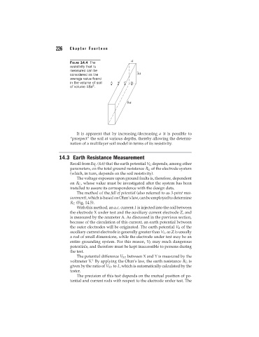
FIGURE 14.4 The
resistivity that is
measured can be
considered as the
average value found
in the volume of soil
3
of volume 18a .
It is apparent that by increasing/decreasing a it is possible to
“prospect” the soil at various depths, thereby allowing the determi-
nation of a multilayer soil model in terms of its resistivity.
14.3 Earth Resistance Measurement
Recall from Eq. (4.6) that the earth potential V G depends, among other
parameters, on the total ground resistance R G of the electrode system
(which, in turn, depends on the soil resistivity).
The voltage exposure upon ground faults is, therefore, dependent
on R G , whose value must be investigated after the system has been
installed to assure its correspondence with the design data.
The method of the fall of potential (also referred to as 3-point mea-
surement), which is based on Ohm’s law, can be employed to determine
R G (Fig. 14.5).
With this method, an a.c. current I is injected into the soil between
the electrode X under test and the auxiliary current electrode Z, and
is measured by the ammeter A. As discussed in the previous section,
because of the circulation of this current, an earth potential between
the outer electrodes will be originated. The earth potential V Z of the
auxiliary current electrode is generally greater than V T , as Z is usually
a rod of small dimensions, while the electrode under test may be an
entire grounding system. For this reason, V Z may reach dangerous
potentials, and therefore must be kept inaccessible to persons during
the test.
The potential difference V XY between X and Y is measured by the
1
voltmeter V. By applying the Ohm’s law, the earth resistance R G is
given by the ratio of V XY to I, which is automatically calculated by the
tester.
The precision of this test depends on the mutual position of po-
tential and current rods with respect to the electrode under test. The