
Page 244 - Electrical Safety of Low Voltage Systems
P. 244
Testing the Electrical Safety 227
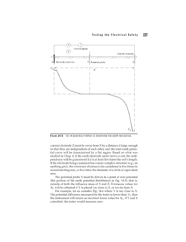
FIGURE 14.5 Fall of potential method to determine the earth resistance.
current electrode Z must be away from X by a distance d large enough
so that they are independent of each other, and the total earth poten-
tial curve will be characterized by a flat region. Based on what was
studied in Chap. 4, if the earth electrode under test is a rod, the inde-
pendency will be guaranteed if d is at least five times the rod’s length.
If the electrode being examined has a more complex structure (e.g., an
earthing grid), the minimum distance to be considered is five times its
maximum diagonal, or five times the diameter of a circle of equivalent
area.
The potential probe Y must be driven in a point at zero potential
(flat portion of the earth potential distribution in Fig. 14.5), that is,
outside of both the influence areas of X and Z. Erroneous values for
R G will be obtained if Y is placed too close to X, or too far from X.
For example, let us consider Fig. 14.6 where Y is too close to X.
The potential difference measured by the tester is lower than V T , thus
the instrument will return an incorrect lower value for R G .IfYand X
coincided, the tester would measure zero.