
Page 249 - Electrical Safety of Low Voltage Systems
P. 249
232 Chapter Fourteen
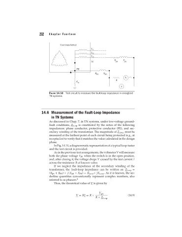
FIGURE 14.10 Test circuit to measure the fault-loop impedance in energized
TN systems.
14.6 Measurement of the Fault-Loop Impedance
in TN Systems
As discussed in Chap. 7, in TN systems, under low-voltage ground-
fault conditions, Z Loop is constituted by the series of the following
impedances: phase conductor, protective conductor (PE), and sec-
ondary winding of the transformer. The magnitude of Z Loop must be
measured at the farthest point of each circuit being protected (e.g., at
receptacles) to verify that it matches the value calculated in the design
phase.
In Fig. 14.10, a diagrammatic representation of a typical loop-tester
and the test circuit is provided.
As in the previous test arrangements, the voltmeter V will measure
both the phase voltage V ph when the switch is in the open position,
and, after closing it, the voltage drops V caused by the test current I
across the resistance R of known value.
If we neglect the impedance of the secondary winding of the
transformer, the fault-loop impedance can be written as: Z Loop =
(R ph + R PE ) + j(X ph + X PE ) = R Loop + jX Loop . As it is known, the un-
derline quantities conventionally represent complex numbers, also
referred to as phasors. 2
Thus, the theoretical value of V is given by
V
ph
V = RI = R × (14.9)
R + Z
Loop