
Page 251 - Electrical Safety of Low Voltage Systems
P. 251
234 Chapter Fourteen
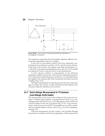
FIGURE 14.12 Test circuit to measure the fault-loop impedance in
de-energized TN systems.
The numerator represents the much simpler algebraic difference be-
tween the magnitudes of the two voltages.
In the case of a prevalently resistive fault-loop, ohmmeters, per-
forming the measurement as per Eq. (14.13), may be used for the test.
If the loop is also reactive, for instance near large transformers (i.e.,
>100 kVA), loop-testers performing the test as per Eq. (14.12) should
be employed in order to prevent errors in the measurement.
A more rigorous method of measurement of the fault-loop
impedance employs loop-testers with a built-in independent genera-
tor G at the power system frequency. In this case, one must disconnect
the supply to the primary side of the transformer and short circuit its
windings (Fig. 14.12).
The fault-loop impedance is directly given by the ratio of the read-
ings of voltage and current. A major drawback of this method is the
necessity to put the substation out of service.
14.7 Touch Voltage Measurement in TN Systems
(Low-Voltage Earth Faults)
The measurement of the actual touch voltage for the worst-case sce-
nario of hand-to-hand contacts occurring between ECPs (e.g., low-
voltage panels) and EXCPs (e.g., cold water pipes) can be carried out
with the method of the fall of potential (Fig. 14.13). If the measure-
ment’s result does not exceed 50 V, the installation can still be consid-
ered safe against indirect contact, even if |Z Loop | is not in compliance
with Eq. (7.5).
With this arrangement, the test current I will circulate through
the protective conductor and the loop impedance will be measured in