
Page 256 - Electrical Safety of Low Voltage Systems
P. 256
Testing the Electrical Safety 239
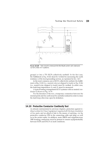
FIGURE 14.18 Test circuit to measure the first-fault current with clamp-on
current probe in IT systems.
groups) or into a TN (ECPs collectively earthed). In the first case,
the fulfillment of Eq. (9.22) must be verified by measuring the earth
resistance of the local grounding system, as explained in Sec. 14.5.
In the most common case of ECPs collectively earthed, the fulfill-
ment of Eq. (9.24) (i.e., neutral wire not shipped to loads) or Eq. (9.26)
(i.e., neutral wire shipped to loads) must be verified. In either case,
the fault-loop impedances Z S and Z must be measured.
S
A typical testing arrangement for IT systems with no neutral con-
ductor is shown in Fig. 14.19.
For the duration of the test, a temporary connection between the
neutral point and the earth must be carefully realized in order to close
the fault-loop otherwise open by definition.
14.10 Protective Conductor Continuity Test
As already substantiated in previous chapters, protection against in-
direct contact for Class I equipment requires both the basic insulation
of live parts and an effective link to the means of earthing, via the
protective conductor (PE) in the connecting cable and plug, as well
as in the socket outlet. In addition, main (MEB) and supplementary
(SB) bonding conductors must be present to ensure equipotentiality
between ECPs and EXCPs in fault conditions.