
Page 284 - Electrical Properties of Materials
P. 284
266 Magnetic materials
materials follow the same pattern. In nickel, another cubic crystal, the direc-
tions of easy and difficult magnetization are the other way round. What matters
is that in most materials magnetization depends on crystallographic directions.
The phenomenon is referred to as anisotropy, and the internal forces which
bring about this property are called anisotropy forces.
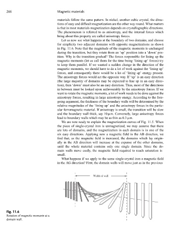
Let us now see what happens at the boundary of two domains, and choose
for simplicity two adjacent domains with opposite magnetizations as shown
in Fig. 11.6. Note that the magnitude of the magnetic moments is unchanged
during the transition, but they rotate from an ‘up’ position into a ‘down’ pos-
ition. Why is the transition gradual? The forces responsible for lining up the
magnetic moments (let us call them for the time being ‘lining up’ forces) try
to keep them parallel. If we wanted a sudden change in the direction of the
magnetic moments, we should have to do a lot of work against the ‘lining up’
forces, and consequently there would be a lot of ‘lining up’ energy present.
The anisotropy forces would act the opposite way. If ‘up’ is an easy direction
(the large majority of domains may be expected to line up in an easy direc-
tion), then ‘down’ must also be an easy direction. Thus, most of the directions
in between must be looked upon unfavourably by the anisotropy forces. If we
want to rotate the magnetic moments, a lot of work needs to be done against the
anisotropy forces, resulting in large anisotropy energy. According to the fore-
going argument, the thickness of the boundary walls will be determined by the
relative magnitudes of the ‘lining up’ and the anisotropy forces in the partic-
ular ferromagnetic material. If anisotropy is small, the transition will be slow
and the boundary wall thick, say 10 μm. Conversely, large anisotropy forces
lead to boundary walls which may be as thin as 0.3 μm.
We are now ready to explain the magnetization curves of Fig. 11.5. When
the piece of single-crystal iron is unmagnetized, we may assume that there
are lots of domains, and the magnetization in each domain is in one of the
six easy directions. Applying now a magnetic field in the AB direction, we
find that, as the magnetic field is increased, the domains which lay origin-
ally in the AB direction will increase at the expense of the other domains,
until the whole material contains only one single domain. Since the do-
main walls move easily, the magnetic field required to reach saturation is
small.
What happens if we apply to the same single-crystal iron a magnetic field
in the AG direction? First, the domain walls will move just as in the previous
Width of wall
Fig. 11.6
Rotation of magnetic moments at a
domain wall.