
Page 307 - Electrical Properties of Materials
P. 307
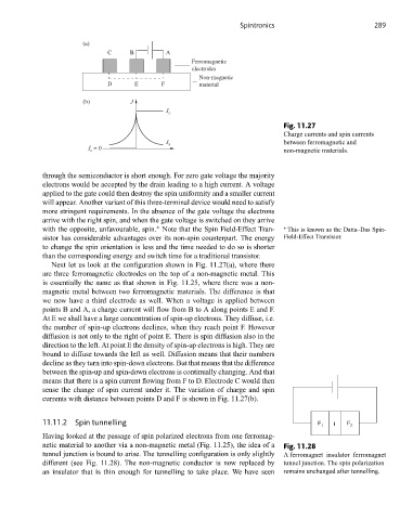
Spintronics                         289

                       (a)
                              C     B        A
                                                    Ferromagnetic
                                                    electrodes
                                                      Non-magnetic
                              D      E      F         material

                       (b)          J
                                             J c
                                                                             Fig. 11.27
                                                                             Charge currents and spin currents
                                             J s                             between ferromagnetic and
                         J = 0                                               non-magnetic materials.
                         c


            through the semiconductor is short enough. For zero gate voltage the majority
            electrons would be accepted by the drain leading to a high current. A voltage
            applied to the gate could then destroy the spin uniformity and a smaller current
            will appear. Another variant of this three-terminal device would need to satisfy
            more stringent requirements. In the absence of the gate voltage the electrons
            arrive with the right spin, and when the gate voltage is switched on they arrive
            with the opposite, unfavourable, spin. Note that the Spin Field-Effect Tran-  ∗  This is known as the Datta–Das Spin-
                                           ∗
            sistor has considerable advantages over its non-spin counterpart. The energy  Field-Effect Transistor.
            to change the spin orientation is less and the time needed to do so is shorter
            than the corresponding energy and switch time for a traditional transistor.
               Next let us look at the configuration shown in Fig. 11.27(a), where there
            are three ferromagnetic electrodes on the top of a non-magnetic metal. This
            is essentially the same as that shown in Fig. 11.25, where there was a non-
            magnetic metal between two ferromagnetic materials. The difference is that
            we now have a third electrode as well. When a voltage is applied between
            points B and A, a charge current will flow from B to A along points E and F.
            At E we shall have a large concentration of spin-up electrons. They diffuse, i.e.
            the number of spin-up electrons declines, when they reach point F. However
            diffusion is not only to the right of point E. There is spin diffusion also in the
            direction to the left. At point E the density of spin-up electrons is high. They are
            bound to diffuse towards the left as well. Diffusion means that their numbers
            decline as they turn into spin-down electrons. But that means that the difference
            between the spin-up and spin-down electrons is continually changing. And that
            means that there is a spin current flowing from F to D. Electrode C would then
            sense the change of spin current under it. The variation of charge and spin
            currents with distance between points D and F is shown in Fig. 11.27(b).


            11.11.2  Spin tunnelling                                                  F 1  I  F 2
            Having looked at the passage of spin polarized electrons from one ferromag-
            netic material to another via a non-magnetic metal (Fig. 11.25), the idea of a  Fig. 11.28
            tunnel junction is bound to arise. The tunnelling configuration is only slightly  A ferromagnet–insulator–ferromagnet
            different (see Fig. 11.28). The non-magnetic conductor is now replaced by  tunnel junction. The spin polarization
            an insulator that is thin enough for tunnelling to take place. We have seen  remains unchanged after tunnelling.