
Page 430 - Electromagnetics
P. 430
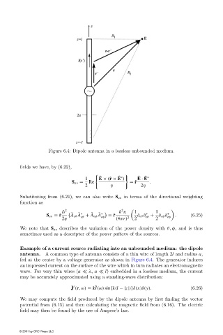
Figure 6.4: Dipole antenna in a lossless unbounded medium.


                        fields we have, by (6.22),

                                                         ˇ
                                                                         ˇ
                                                   1     E × (ˆ r × E )  E · E
                                                                            ˇ ∗
                                                                 ˇ ∗
                                             S av =  Re               = ˆ r   .
                                                   2          η           2η
                        Substituting from (6.21), we can also write S av in terms of the directional weighting
                        function as
                                           2                      2
                                             ˇ
                                                      ˇ
                                          ˇ ω                    k η    1    ∗   1    ∗
                                                ˇ ∗
                                                         ˇ ∗
                                                                                  ˇ
                                   S av = ˆ r  A eθ A + A eφ A  eφ  = ˆ r  ˇ a eθ ˇ a + a eφ ˇ a eφ  .  (6.25)
                                                 eθ
                                                                            eθ
                                         2η                     (4πr) 2  2       2
                        We note that S av describes the variation of the power density with θ, φ, and is thus
                        sometimes used as a descriptor of the power pattern of the sources.
                        Example of a current source radiating into an unbounded medium: the dipole
                        antenna.  A common type of antenna consists of a thin wire of length 2l and radius a,
                        fed at the center by a voltage generator as shown in Figure 6.4. The generator induces
                        an impressed current on the surface of the wire which in turn radiates an electromagnetic
                        wave. For very thin wires (a   λ, a   l) embedded in a lossless medium, the current
                        may be accurately approximated using a standing-wave distribution:
                                             ˜ i
                                                       ˜
                                             J (r,ω) = ˆ zI(ω) sin [k(l −|z|)] δ(x)δ(y).       (6.26)
                        We may compute the field produced by the dipole antenna by first finding the vector
                        potential from (6.15) and then calculating the magnetic field from (6.16). The electric
                        field may then be found by the use of Ampere’s law.


                        © 2001 by CRC Press LLC