Page 118 -
P. 118

1. The voltage across a resistor is given, using Ohm’s law, by:
                                                         V (t) = RI(t)                     (4.25)
                                                          R
                                   where R is the resistance, I is the current, and where R is measured
                                   in Ohms.
                                2. The voltage across a capacitor is proportional to the magnitude of
                                   the charge that accumulates on either plate, that is:

                                                           Qt() ∫  It dt()
                                                     Vt() =     =                          (4.26)
                                                      C
                                                            C       C
                                   The second equality reflects the relation of the current to the charge.
                                   C is the capacitance and, as previously pointed out, is measured
                                   in Farads.
                                3. The voltage across an inductor can be deduced from Lenz’s law,
                                   which stipulates that the voltage across an inductor is proportional
                                   to the time derivative of the current going through it:

                                                        Vt() =  L  dI t()                  (4.27)
                                                          L
                                                                 dt
                                   where L is the inductance and is measured in Henrys.
                              From these expressions for the voltage drop across each of the passive ele-
                             ments in a circuit, and using the Kirchoff voltage law, it is then an easy matter
                             to write down the differential equations describing, for example, a series RC
                             or an RLC circuit.

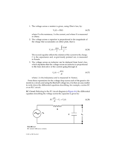
                             RC Circuit: Referring to the RC circuit diagram in Figure 4.4, the differential
                             equation describing the voltage across the capacitor is given by:

                                                         dV C
                                                      RC     + V =  V t()                  (4.28)
                                                                    s
                                                                C
                                                          dt


                                                             R
                                              V S
                                                                         C             V C


                              FIGURE 4.4
                              RC circuit with an ac source.


                             © 2001 by CRC Press LLC
   113   114   115   116   117   118   119   120   121   122   123