Page 201 - Elements of Chemical Reaction Engineering 3rd Edition
P. 201

Sec. 4.4   Pressure Drop in Reactors                          173

                                             1.000
                                     __
                                     IKEY:
                                     -Xl     0.800
                                     -. x2
                                     .-y1
                                     -- y2
                                             11.600
                                             0.400


                                             n. 200

                                              ci. oao
                                                  0.000    0. so0   o.ao0    1.200    1.600    :!.ooo
                                                                          u-10-5
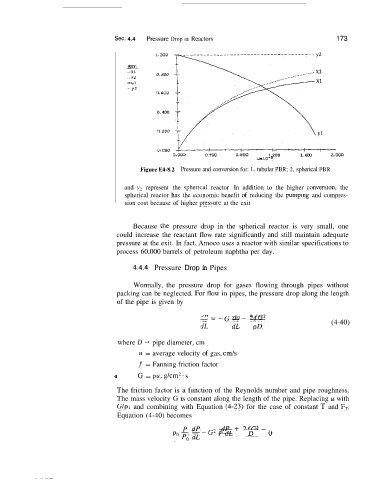
                                         Figure 64-8.2  Pressure and conversion for: 1,  tubular PBR; 2, spherical PBR.

                                    and  )?  represent  the  sphencal  reactor  In  addition  to  the  higher  conversiori,  the
                                    spherical  reactor  has  the  economic benefit of  reducing  the pumpmg  and compres-
                                    sion cost because of  higher preswre at the exit


                                       Because  the  pressure  drop  in  the  spherical  reactor  is  very  small,  one
                                  could increase  the reactant  flow rate  significantly and still maintain  adequate
                                  pressure at the exit. In fact, Amoco uses a reactor with similar specifications to
                                  process 60,000 barrels of petroleum naphtha per day.
                                       4.4.4  Pressure  Drop in Pipes


                                       Wormally,  the  pressure  drop  for  gases  flowing  through  pipes  without
                                  packing can be neglected. For flow in pipes, the pressure drop along the length
                                  of the pipe is given  by

                                                          sip           2fG2                   (4-40)
                                                          -=-G--- du
                                                          dt       dL    pD

                                  where D  = pipe diameter, cm
                                        11  = average velocity of gas, cmk
                                        f  = Fanning friction factor
                                 4      G = pit, g/cm2. s
                                  The friction factor is a function of  the  Reynolds number and pipe roughness.
                                  The mass velocity G is constant along the length of the pipe. Replacing u with
                                  G/p,  and  combining  with  Equation  (4-23) for  the  case of  constant T  and  FT,
                                  Equation (4-40) becomes

                                                     P  dP      dP    2fG2 -o
                                                  Pop,         PdL+  7-
   196   197   198   199   200   201   202   203   204   205   206