
Page 108 - Embedded Microprocessor Systems Real World Design
P. 108
Microprocessor Clocks
I mentioned crystals and ceramic resonators earlier in the chapter. The selection
of a crystal reference for a microprocessor often seems to be a source of mystery,
so this section will try to clear it up a little.
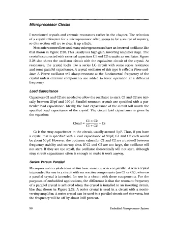
Most microcontrollers and many microprocessors have an internal oscillator like
that shown in Figure 2.28. This usually is a high-gain, inverting amplifier stage. The
crystal is connected with external capacitors C1 and C2 to make an oscillator. Figure
2.28 also shows the oscillator circuit with the equivalent circuit of the crystal. At
resonance, the crystal looks like a series LC circuit with some series resistance
and some parallel capacitance. A crystal oscillator of this type is called a Pier& osn'l-
lutur. A Pierce oscillator will always resonate at the fundamental frequency of the
crystal unless external components are added to force operation at a different
frequency.
Load Capacitance
Capacitors C1 and C2 are needed to allow the oscillator to start. C1 and C2 are typi-
cally between 20pf and 100pf. Parallel resonant crystals are specified with a par-
ticular load capacitance. Ideally, the load capacitance of the circuit will match the
specified load capacitance of the crystal. The circuit load capacitance is given by
the equation:
c1 x c2
Cload = - + cs
c1+ c2
Cs is the stray capacitance in the circuit, usually around 5pF. Thus, if you have
a crystal that is specified with a load capacitance of 30pF, C1 and C2 each would
be about 50pF. However, the optimum values for C1 and C2 are a tradeoff between
frequency stability and startup time. If C1 and C2 are too large, the oscillator will
not start. If they are too small, the oscillator theoretically will not start, although
stray circuit capacitance often is enough to make it work anyway.
Series Versus Parallel
Microprocessor crystals come in two basic varieties, series or parallel. A series crystal
is intended for use in a circuit with no reactive components (no C1 or C2), whereas
a parallel crystal is intended for use in a circuit with these components. For the
purposes of embedded applications, the difference is that the resonant frequency
of a parallel crystal is achieved when the crystal is installed in an inverting circuit,
like that shown in Figure 2.28. A series crystal is used in a circuit with a nonin-
verting amplifier. A series crystal can be used in a parallel circuit and vice-versa, but
the frequency will be off by about 0.02 percent.
90 Embedded Microprocessor Systm