
Page 133 - Embedded Microprocessor Systems Real World Design
P. 133
The lOOcount encoder produces one pulse every 3.6 degrees of rotation
(360/100). This is true at any motor speed. However, the input capture reference
clock is fixed, so its accuracy (in degrees of rotation) vanes with the motor speed.
At lORPM, each reference clock corresponds to:
Encoder Pulses Deg 1 Seconds
16.66 x 3.6
Encoder Pulse 1,000,000 Reference Clock
= 60 x 10” degrees per reference clock
At 2000RPM, this becomes .012 degrees. While either of these is probably ade-
quate for a motor control application, the principle is important; at faster RF’M,
the accuracy of the reference clock with respect to the input signal is less.
PWM Output Similar considerations apply to timer outputs. If you are using an
8-bit timer to generate a PWM signal, the output duty cycle can only be changed
by one timer count, or 1 in 256. This results in a duty cycle resolution of .3 percent.
Note, though, that this applies only if the timer is allowed to run a full 256 counts.
If you are using an 8-bit timer but only 100 counts for the PWM period, then one
step is 1 percent of the total period. In this case, the best resolution you can get is
I percent. This is sufficient for many applications but is inadequate for others. In
an application in which you vary the PWM period and duty cycle, you need to be
sure that the resolution at the fastest period (least number of timer counts per
cycle) is adequate for the application.
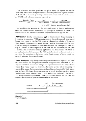
Count Ambiguity Any time you are using timers to measure a period, you must
take into account the ambiguity in the result. Say you have a timer with a 1 mil-
lisecond resolution and you are using input capture to measure the time between
events. Two events occur, one measuring 51 counts and the other measuring 52
counts. That means the two events occurred a millisecond apart, right? Well, maybe
not. As Figure 3.7 shows, the two events could be nearly simultaneous. One occurs
just before the count rolls over from 51 to 52, and one occurs just after the rollover.
Any time you measure period with a timer, you can only assume that the value you
read has an accuracy of plus or minus the timer resolution.
1
e MILLISECOND
1
COUNTER sol5 1 52 I 53 I 54
EVENT 1 OCCURS .rpI
EVENT 2 OCCURS f
~ ~~ ~~~ ~~ ~
Figure 3.7
Count Ambiguity.
114 Embedded MicrOprocessor System