
Page 202 - Embedded Microprocessor Systems Real World Design
P. 202
START
BIT
D3 SERIAL STATUS OUTPUT WAVEFORM.
l-v
DATA = 10 (1010 BINARY)
START
''? D1 D3
SERIAL STATUS OUTPUT WAVEFORM,
DATA= 11 (1011 BINARY)
SERIAL STATUS USING SELF-CLOCKING
SCHEME (3 BITS SHOWN)
DATA = 101
CLOCK BITS DATA PULSES IF BIT=l
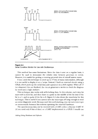
Figure 6.4
Serial Condition Monitor for Use with Oscilloscope.
This method has some limitations. Since the data is sent on a regular basis, it
cannot be used to determine the relative time between processes or events.
However, it is useful for getting a running pictorial view of overall system status.
I have used this technique to send up to 17 bits of status information, although
it is not useful to display it on a 'scope. Instead, I built an external circuit, using a
CPLD, which picks up the serial data and captures it in a shift register. When all 17
(or whatever) bits are finished, the circuit generates a strobe to clock the diagnos-
tic word into a logic analyzer.
This technique also works with self-clochng data. In this scheme, each data bit
starts with a clock bit, and then there is a pulse in the middle of the bit time if the
bit is a 1, and no pulse if the bit is 0. Figure 6.4 also shows the waveform for this
technique. This is useful if you cannot turn the interrupts off long enough to send
an entire diagnostic word. Because each bit is self-clocking, you can turn interrupts
on momentarily between bits without upsetting the external hardware.
The asynchronous data can be received with a UMT, either a discrete UART IC
(if you need only 8 bits of data) or a UART implemented in a CPLD. I usually use
Adding Debug Hardware and Software 183