
Page 203 - Embedded Microprocessor Systems Real World Design
P. 203
BIT COUNTER
OUTPUT AFTER STROBE LAST BIT
PULSES
IS SHIFTED IMO
SHIFT REGISTER
DATA
SHIFT
-
REGISTER
: AS MANY OUTPUT
SERIAL INPUT DATA BITS AS SOFWARE
: TRANSMITS
a
-
a
IN
REF CLOCK
I I
SERIAL INPUT DATA I I
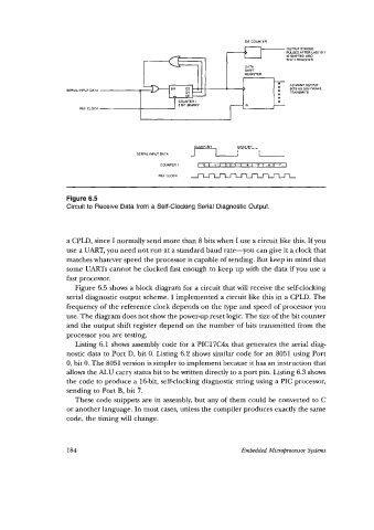
Figure 6.5
Circuit to Receive Data from a Self-Clocking Serial Diagnostic Output.
a CPLD, since I normally send more than 8 bits when I use a circuit like this. If you
use a UART, you need not run at a standard baud rate-you can give it a clock that
matches whatever speed the processor is capable of sending. But keep in mind that
some UARTs cannot be clocked fast enough to keep up with the data if you use a
fast processor.
Figure 6.5 shows a block diagram for a circuit that will receive the self-clocking
serial diagnostic output scheme. I implemented a circuit like this in a CPLD. The
frequency of the reference clock depends on the type and speed of processor you
use. The diagram does not show the power-up reset logic. The size of the bit counter
and the output shift register depend on the number of bits transmitted from the
processor you are testing.
Listing 6.1 shows assembly code for a PIC17C4x that generates the serial diag-
nostic data to Port D, bit 0. Listing 6.2 shows similar code for an 8051 using Port
0, bit 0. The 8051 version is simpler to implement because it has an instruction that
allows the ALU carry status bit to be written directly to a port pin. Listing 6.3 shows
the code to produce a lcbit, self-clocking diagnostic string using a PIC processor,
sending to Port B, bit 7.
These code snippets are in assembly, but any of them could be converted to C
or another language. In most cases, unless the compiler produces exactly the same
code, the timing will change.
184 Embedded Micropocessw Systm