
Page 186 - Academic Press Encyclopedia of Physical Science and Technology 3rd Chemical Engineering
P. 186
P1: GGY Final Pages
Encyclopedia of Physical Science and Technology EN004D-156 June 8, 2001 15:28
Cryogenic Process Engineering 29
air separation, and low-temperature hydrocarbon process-
ing. Additional design details for plate–fin exchangers are
available in most heat-exchanger texts.
3. Reversing Exchangers
Operation of low-temperature processes on a continuous
basis necessitates the removal of all impurities that would
solidify on cooling to very low temperatures. This cleanup
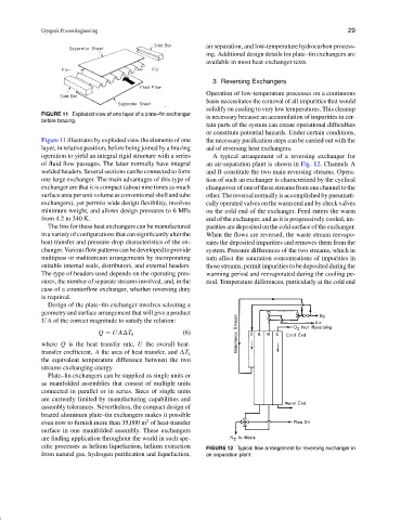
FIGURE 11 Exploded view of one layer of a plate–fin exchanger
is necessary because an accumulation of impurities in cer-
before brazing.
tain parts of the system can create operational difficulties
or constitute potential hazards. Under certain conditions,
Figure 11 illustrates by exploded view the elements of one the necessary purification steps can be carried out with the
layer, in relative position, before being joined by a brazing aid of reversing heat exchangers.
operation to yield an integral rigid structure with a series A typical arrangement of a reversing exchanger for
of fluid flow passages. The latter normally have integral an air-separation plant is shown in Fig. 12. Channels A
welded headers. Several sections can be connected to form and B constitute the two main reversing streams. Opera-
one large exchanger. The main advantages of this type of tion of such an exchanger is characterized by the cyclical
exchanger are that it is compact (about nine times as much changeoverof one ofthese streams from one channeltothe
surface area per unit volume as conventional shell and tube other.Thereversalnormallyisaccomplishedbypneumati-
exchangers), yet permits wide design flexibility, involves cally operated valves on the warm end and by check valves
minimum weight, and allows design pressures to 6 MPa on the cold end of the exchanger. Feed enters the warm
from 4.2 to 340 K. end of the exchanger, and as it is progressively cooled, im-
The fins for these heat exchangers can be manufactured purities are deposited on the cold surface of the exchanger.
in a variety of configurations that can significantly alter the When the flows are reversed, the waste stream reevapo-
heat transfer and pressure drop characteristics of the ex- rates the deposited impurities and removes them from the
changer. Various flow patterns can be developed to provide system. Pressure differences of the two streams, which in
multipass or multistream arrangements by incorporating turn affect the saturation concentrations of impurities in
suitable internal seals, distributors, and external headers. those streams, permit impurities to be deposited during the
The type of headers used depends on the operating pres- warming period and reevaporated during the cooling pe-
sures, the number of separate streams involved, and, in the riod. Temperature differences, particularly at the cold end
case of a counterflow exchanger, whether reversing duty
is required.
Design of the plate–fin exchanger involves selecting a
geometry and surface arrangement that will give a product
UA of the correct magnitude to satisfy the relation:
(6)
Q = UA T e
where Q is the heat transfer rate, U the overall heat-
transfer coefficient, A the area of heat transfer, and T e
the equivalent temperature difference between the two
streams exchanging energy.
Plate–fin exchangers can be supplied as single units or
as manifolded assemblies that consist of multiple units
connected in parallel or in series. Sizes of single units
are currently limited by manufacturing capabilities and
assembly tolerances. Nevertheless, the compact design of
brazed aluminum plate–fin exchangers makes it possible
2
even now to furnish more than 35,000 m of heat-transfer
surface in one manifolded assembly. These exchangers
are finding application throughout the world in such spe-
cific processes as helium liquefaction, helium extraction FIGURE 12 Typical flow arrangement for reversing exchanger in
from natural gas, hydrogen purification and liquefaction, air separation plant.