
Page 188 - Academic Press Encyclopedia of Physical Science and Technology 3rd Chemical Engineering
P. 188
P1: GGY Final Pages
Encyclopedia of Physical Science and Technology EN004D-156 June 8, 2001 15:28
Cryogenic Process Engineering 31
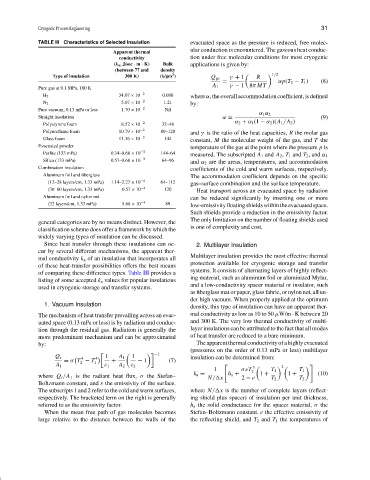
TABLE III Characteristics of Selected Insulation evacuated space as the pressure is reduced, free molec-
ular conduction is encountered. The gaseous heat conduc-
Apparent thermal
conductivity tion under free molecular conditions for most cryogenic
(k a , J/sec · m · K) Bulk applications is given by:
(between 77 and density
3
Type of insulation 300 K) (k/gm ) Q gc γ + 1 R 1/2
= αp(T 2 − T 1 ) (8)
Pure gas at 0.1 MPa, 180 K A 1 γ − 1 8π MT
H 2 34.07 × 10 −2 0.080 where α, the overall accommodation coefficient, is defined
N 2 5.67 × 10 −2 1.21 by:
Pure vacuum, 0.13 mPa or less 1.70 × 10 −2 Nil
α 1 α 2
Straight insulation α = (9)
Polystyrene foam 8.52 × 10 −2 32–48 α 2 + α 1 (1 − α 2 )(A 1 /A 2 )
Polyurethane foam 10.79 × 10 −2 80–128 and γ is the ratio of the heat capacities, R the molar gas
Glass foam 11.36 × 10 −2 144 constant, M the molecular weight of the gas, and T the
Evacuated powder temperature of the gas at the point where the pressure p is
Perlite (133 mPa) 0.34–0.68 × 10 −2 144–64
measured. The subscripted A 1 and A 2 , T 1 and T 2 , and α 1
Silica (133 mPa) 0.57–0.68 × 10 −2 64–96 and α 2 are the areas, temperatures, and accommodation
Combination insulation coefficients of the cold and warm surfaces, respectively.
Aluminum foil and fiberglass The accommodation coefficient depends on the specific
(12–28 layers/cm, 1.33 mPa) 1.14–2.27 × 10 −4 64–112 gas–surface combination and the surface temperature.
(30–60 layers/cm, 1.33 mPa) 0.57 × 10 −4 120 Heat transport across an evacuated space by radiation
Aluminum foil and nylon net can be reduced significantly by inserting one or more
(32 layers/cm, 1.33 mPa) 5.68 × 10 −4 89 low-emissivityfloatingshieldswithintheevacuatedspace.
Such shields provide a reduction in the emissivity factor.
The only limitation on the number of floating shields used
general categories are by no means distinct. However, the
is one of complexity and cost.
classification scheme does offer a framework by which the
widely varying types of insulation can be discussed.
Since heat transfer through these insulations can oc- 2. Multilayer Insulation
cur by several different mechanisms, the apparent ther-
Multilayer insulation provides the most effective thermal
mal conductivity k a of an insulation that incorporates all
protection available for cryogenic storage and transfer
of these heat-transfer possibilities offers the best means
systems. It consists of alternating layers of highly reflect-
of comparing these difference types. Table III provides a
ing material, such as aluminum foil or aluminized Mylar,
listing of some accepted k a values for popular insulations
and a low-conductivity spacer material or insulator, such
used in cryogenic storage and transfer systems.
as fiberglass mat or paper, glass fabric, or nylon net, all un-
der high vacuum. When properly applied at the optimum
1. Vacuum Insulation
density, this type of insulation can have an apparent ther-
The mechanism of heat transfer prevailing across an evac- mal conductivity as low as 10 to 50 µW/m · K between 20
uated space (0.13 mPa or less) is by radiation and conduc- and 300 K. The very low thermal conductivity of multi-
tion through the residual gas. Radiation is generally the layer insulations can be attributed to the fact that all modes
more predominant mechanism and can be approximated of heat transfer are reduced to a bare minimum.
by: Theapparentthermalconductivityofahighlyevacuated
(pressures on the order of 0.13 mPa or less) multilayer
−1
Q r 4 4 1 A 1 1 insulation can be determined from:
= σ T − T 1 + − 1 (7)
2
A l ε 1 A 2 ε 2 3
2
1 σeT 2 T 1 T 1
where Q r /A 1 is the radiant heat flux, σ the Stefan– k a = N/ x h s + 2 − e 1 + T 2 1 + T 2 (10)
Boltzmann constant, and ε the emissivity of the surface.
The subscripts 1 and 2 refer to the cold and warm surfaces, where N/ x is the number of complete layers (reflect-
respectively. The bracketed term on the right is generally ing shield plus spacer) of insulation per unit thickness,
referred to as the emissivity factor. h s the solid conductance for the spacer material, σ the
When the mean free path of gas molecules becomes Stefan–Boltzmann constant. e the effective emissivity of
large relative to the distance between the walls of the the reflecting shield, and T 2 and T 1 the temperatures of