
Page 149 - Academic Press Encyclopedia of Physical Science and Technology 3rd Organic Chemistry
P. 149
P1: GTY/GWT P2: GLM Final
Encyclopedia of Physical Science and Technology EN006K-933 July 12, 2001 15:6
Fuel Chemistry 259
FIGURE 3 Schematic diagram of a traveling grate stroker.
to a minimum. Ash particles produced are dropped into a
refuse pit on the other side of the combustion chamber. As
shown in Fig. 4, the oxidant and the products of combus-
tion have to travel through the layer of ash produced. This
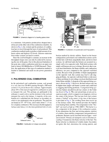
FIGURE 5 A schematic of a pulverized coal firing system.
combustion method tends to produce a high amount of un-
burnt carbon and high(er) CO levels. Gaseous emissions
from stoker systems are hard to control. bustion method by electric utilities. Based on the burner
Since the coal bed height is constant, an increase in the configuration, pulverized coal combustion systems can be
throughput (larger size) can only be achieved by increas- divided into wall-fired, tangentially fired, and down-fired
ing the size of the grate. Due to this physical limitation of systems. In wall-fired units the burners are mounted on a
the grate size, stoker combustion units have an upper size single wall or two opposite walls. Wall-fired systems with
limit of about 100 MMBtu/hr or 30 MW(thermal). There- single wall burners are easy to design. However, due to un-
fore, the application of this type of combustion method is even heat distribution, the flame stability and combustion
limited to industrial and small on-site power generation efficiency are poor compared to the opposed wall-fired
units. system. Because of the possibility of flame impingement
on the opposite wall, this system may lead to ash slag-
ging problems. An opposite wall-fired boiler avoids most
V. PULVERIZED COAL COMBUSTION of these problems by providing even heat distribution and
better flame stability. A diagram of the opposed firing sys-
In the pulverized coal combustion system, coal ground tem is shown in Fig. 5. However, the heat release rate can
to a very fine size (70–80% passing through a 200-mesh be higher than single wall burner systems and could lead
screen or 75 µm) is blown into a furnace. Approximately to slagging and fouling problems. A tangential firing sys-
about 10% of the total air required for combustion is used tem has burners installed in all four corners of the boiler
to transport the coal. This primary air, preheated in the (as shown in Fig. 6). The coal and primary air jets are is-
airheater, is used to drive out the moisture in the coal and sued at an angle, which is tangent to an imaginary circle at
transport the coal to the furnace. A majority of the com- the center of the furnace. The four jets from four corners
bustion air is admitted into the furnace as secondary air, create a “fireball” at the center. A top view of the furnace
which is also preheated in the air preheater. The particles is provided in Fig. 6. The swirling flame then travels up
5
6◦
are heated at 10 –10 C/sec, and it takes about 1–1.5 sec to the furnace outlet. This method provides the highest
for complete combustion. This increases the throughput to even heating flame stability. The temperature in the “fire-
furnace and, hence, it is the most preferred form of com- ball” can reach as high as 1700–1800 C. The burner is a
◦
key component in the design of the combustion system.
It also determines the flow and mixing patterns, ignition
of volatiles, flame stability, temperature, and generation of
pollutants. Burners can be classified into two types—swirl
and nonswirl. Primary air transports coal at velocities ex-
ceeding 15 meters/sec (the flame velocity) of the fuel. The
flame velocity is a function of volatile matter. Secondary
FIGURE 4 Combustion of a large coal particle. air ignites the fuel, determines the mixing pattern, and